The low-power general-purpose silicon NPN BJTs like BC107, BC108 & BC109 were created by Mullard and Philips in 1963 but introduced in April 1966. It is a bipolar junction transistor within a TO-18 metal can package, used for switching and amplification purposes. Generally, BJTs are solid-state devices that control the current flow between the collector & the emitter terminals by using the base terminal. So the current supply throughout the base terminal controls the current supply between the emitter and collector. This article discusses an overview of the BC109 transistor, pinout, specifications, circuit, working, and applications.
What is BC109 Transistor?
The BC109 is an NPN silicon planar epitaxial transistor available in the TO-18 metal case. This transistor is designed mainly for general amplification and switching purposes, so applicable in low noise input stages, driver stages, and TV receiver’s signal processing circuits. The maximum CE voltage of this transistor is 20Volts which means the transistor can drive 20V of maximum load voltage. In addition, the max collector dissipation is approximately 300mW & the DC gain value ranges from 200 to 800 with 4dB of good noise figure.
BC109 transistor is accessible in three special hFE values; BC109 hFE value ranges from 200 to 800, BC109C hFE value ranges from 420 to 800 and BC109B hFE value ranges from 200-450.
While looking for a suitable transistor for your application based on a few factors, it is very important to look into a few points on How to Select a Transistor.
Working
BC109 transistor is a semiconductor device used for amplifying or switching electronic signals as well as electrical power. Whenever voltage (or) current is applied to one pair of the terminals of the transistor then it controls the current throughout another pair of transistor terminals. So, due to the higher output power than the (input power, the transistor amplifies a signal.
Pin Configuration:
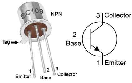
The pin configuration of the BC109 transistor is shown below. This transistor includes three terminals that carry electrical current & connect the transistor to exterior circuits.

BC109 Transistor Pin Configuration
- Pin-1 (Emitter): The Emitter terminal is a negative lead which provides a large segment of the majority charge carrier.
- Pin-2 (Base): The base is a middle terminal of the transistor which is used to bias the transistor by turning ON and OFF.
- Pin-3 (Collector): The collector terminal is a positive lead that gathers the majority of charge carriers supplied by the emitter terminal.
Features & Specifications:
The features and specifications of the BC109 transistor include the following.
- It is a three-terminal NPN transistor.
- This transistor is available in the TO-18 Package.
- The transistor material is Si.
- Its maximum Collector Current or IC is 100mA.
- Its CE voltage or VCE maximum is 20V.
- Maximum CB voltage or VCB is 30V.
- The emitter to base voltage or VBE maximum is 5V.
- Maximum Collector dissipation or Pc is 300 Milliwatt.
- The transition frequency or fT maximum is 100 MHz.
- DC gain or hFE minimum and maximum ranges from 200 to 800.
- The maximum noise figure is 1.5 dB.
- Maximum operating and storage temperature must range from -65 to 150 Centigrade.
- Collector power dissipation or Pc maximum is 0.3 W.
- Collector current or Ic max is 0.1 A.
- Collector capacitance or Cc is 5 pF.
Equivalent & Complementary Transistors
Equivalent BC109 transistors are; BC107, BC108, BC584, BC173, BC239 and 3DG120A. The complementary BC109 transistor is the BC179 PNP transistor. The BC109 transistor SMD version is MMBTH10 in SOT-23.
Replacing a suitable transistor in any circuit based on requirement is very important. To know how to replace it, please refer to this; Replacing Transistors in Electronic Circuits: Factors and Considerations.
How to use BC109 Transistor securely in a Circuit for a Long Time?
To use the BC109 transistor very securely in a circuit for a long time, it is suggested not to use it on its absolute maximum ratings & stay below 20% always. The max collector current of this transistor is 100mA thus do not drive>80mA load. The maximum CE voltage is around 20V therefore do not drive >16V load. Always operate and store this transistor at> -65 °C and < 150°C.
Audio Mixer Circuit with BC109 Transistor
An audio mixer is a device, used to blend several audio signals into a single output signal. To accomplish this, several audio mixers utilize various transistors, but the single-transistor audio mixer is a very simple and efficient alternative.
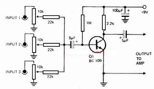
The required components to make this audio mixer circuit mainly include; a BC109 transistor, 100uf capacitor, 5uf capacitors, 22k resistors, 2.2k resistor, 10k potentiometer, and 1M resistor. Connect the circuit as per the diagram shown below.

Audio Mixer Circuit with BC109 Transistor
Working
The BC109 is an NPN low-noise and small-signal transistor. This transistor has a gain of around 200 and is used commonly in audio applications like; amplifiers and preamplifiers. So, BC109 transistor in an audio mixer circuit can be utilized as a single amplifying element.
The audio mixer circuit with BC109 transistor includes a few basic electronic components. Here, the input signals are connected to the transistor’s base terminal throughout the capacitor to block any DC components. So the variable resistor permits for the volume level adjustment & the resistors around the transistor bias it into the linear operation region. The output is received from the transistor’s collector terminal via a capacitor and is connected to a load like a speaker or headphones.
Thus, a single-transistor audio mixer circuit with a BC109 transistor is a very simple & effective design, used mainly for small-scale audio mixing applications. So, this circuit is a great option for students, DIY enthusiasts, and hobbyists. However, it may not be appropriate for larger-scale mixing applications (or) those that need a high range of fidelity or precision. In general, the BC109 is a great choice for those who are looking to make a basic audio mixer.
Connecting a base resistor to the base terminal of the transistor is mandatory to avoid it being damaged. So, Please refer to this link for; Choosing Base Resistance for Transistors in Electronic Circuits.
Automatic Heat Detector Circuit
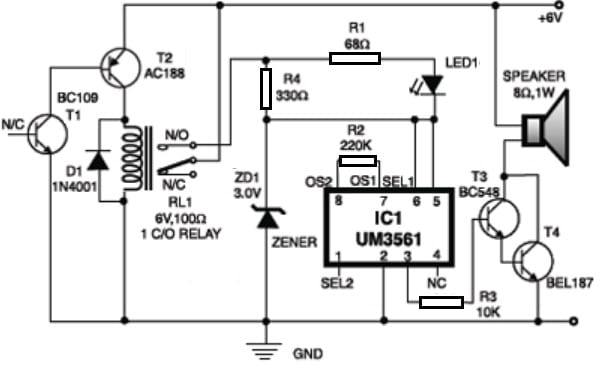
The automatic heat detector circuit is shown below which utilizes a complementary pair of BC109 NPN and AC188 PNP transistors to detect heat within the vicinity & generate a siren. The required components to make this circuit mainly include; UM3561 IC, complementary BC109 & AC188 transistors, BEL187 and BC548 transistors, 1N40001 diode, 6V 100 Ohms relay, ZD1 zener diode, LED, speaker, resistors like; 68ohms, 330ohms, 220 ohms and 10K. Connect the circuit as per the diagram shown below.

Automatic Heat Detector Circuit
Working
In the first part of the above circuit, the collector terminal of the T1 transistor is connected simply to the base terminal of transistor T2 whereas the collector terminal of transistor T2 transistor is connected to the RL1 relay. In the second part of the circuit has UM3561 IC which generates the fire-brigade siren sound.
Pins 5 & 6 of this IC are connected simply to the +3V supply whenever the relay is in energized condition while pin 2 is grounded. An R2 resistor is connected across pins 7 & 8 for fixing the inbuilt oscillator’s frequency, so the output is obtainable from pin 3.
The two BC147 & BEL187 transistors are connected simply in a Darlington pattern for amplifying the sound from IC. Here R4 resistor with a 3V zener in series is utilized to provide the 3Volts supply to IC whenever the relay is in energized condition. Thus, LED1 is connected with a 68-ohm resistor in series across R4 resistor which glows whenever the siren is turned on.
To test this circuit, place a burning match stick near to BC109 transistor then this causes the resistance of its EC junction to go low because of an increase in temperature & it begins conducting. So, the T2 transistor also conducts at the same time, because its base terminal is connected to the collector terminal of the T1 transistor. Thus, the RL1 relay strengthens & turns on the siren circuit to generate a fire brigade siren’s loud sound.
Advantages & Disadvantages
The advantages of the BC109 transistor include the following.
- It is a low-power, general-purpose transistor.
- This transistor has 4 dB of low noise figure.
- Its transition frequency is 100 MHz.
- The BC109 transistor has 200°C of maximum operating temperature.
- It can be utilized in different applications.
- It can be utilized to drive loads <100mA.
The disadvantages of the BC109 transistor include the following.
- This transistor is very sensitive to temperature,
- It can be damaged because of the thermal runway (or) second breakdown.
- Its reverse blocking capacity is extremely low.
- If this transistor is not biased properly it may get damaged.
- If this transistor is turned ON & OFF too fast, then it can overheat & harm the nearby circuitry.
BC109 Transistor Applications
The applications of the BC109 transistor include the following.
- BC109 is a general-purpose transistor, used in general-purpose applications.
- It can be utilized to drive <100mA loads.
- The low noise figure of this transistor makes it perfect to utilize for preamplification, audio amplification & any electronic signal amplification.
- This transistor is used in RF circuits <100MHz.
- These transistors are used in RF circuits, Darlington pairs, audio amplifier circuits, and switching loads <100mA.
- This transistor can be utilized in DIY kits.
Please refer to this link for the BC109 Transistor Datasheet.
Thus, this is an overview of the BC109 transistor, pinout, features, specifications, circuit, working, and applications. This is an NPN, through-hole silicon planar epitaxial transistor available in the TO-18 metal can package. So this transistor is used in different applications like; signal processing, portable devices, power management, and industrial and consumer electronics. This transistor offers a cost-effective and reliable solution for different electronic applications. Here is a question for you, what is BC108 transistor?