An electronic circuit that makes a comparison between two voltage levels or input signals is called a comparator. This IC compares the two applied inputs to it & generates an output that specifies which of the inputs is lesser or greater. If the non-inverting input is higher as compared to the inverting input, then output goes high and if the inverting input is higher as compared to the non-inverting, then output goes low. There are different types of comparator ICs like LM311, LM393, LM2903 and LM2901. This article provides brief information on one of the comparator ICs namely LM393 comparator IC.
What is LM393 Comparator IC?
LM393 is a comparator IC that has internally two high-accuracy op-amps that operate with a single (or) dual power supply. Each op amp accepts two inputs mainly for comparison and measures which i/p voltage is the larger and then it provides o/p. These ICs are available in different packages like; 8 Pin SO-8, DIP, etc. This IC is used in a wide range of applications because of its wide voltage supply range. These ICs are best for consumer, industrial electronics & automotive applications because of their low input offset voltage specifications of 2.0 mV. The highest output current of this IC is 20mA which is sufficient to drive logic systems, transistors, microcontrollers & logic devices.
Pin Configuration:
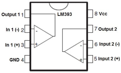
The pin configuration of the LM393 comparator IC is shown below. This IC includes eight pins which are discussed below.

LM393 Comparator Pin Configuration
- Pin-1 (Output1): This is the o/p pin of the first op-amp.
- Pin-2 (Input1): This is an inverting i/p pin of the first op-amp.
- Pin-3 (Input1+): This is a non-inverting i/p pin of the first op-amp.
- Pin-4 (VEE/GND): This is the GND pin of the comparator IC which is connected to the negative terminal of the voltage supply.
- Pin-5 (Input2+): This is a non-inverting i/p pin of the second op-amp.
- Pin-6 (Input2-): This is an inverting i/p pin of the second op-amp.
- Pin-7 (Output2): This is the o/p pin of the second op-amp.
- Pin-8 (VCC): This is the positive (+ve) pin of the IC which is connected to the positive terminal of the voltage supply.
The internal structure of the LM393 comparator IC follows as; this IC has two operational amplifiers internally. The negative inputs of these two op-amps are connected simply to the pin-4 of IC whereas positive inputs of these ICs are connected to pin-8 of IC.
The inverting input of the first op-amp is connected to pin-2 of IC whereas the non-inverting i/p is connected to pin-3 of IC. The output of the first op-amp is connected to pin-1 of the IC. The inverting input of the second op-amp is connected to the pin-6 of IC whereas the non-Inverting input is connected to pin-5 of the IC. The first op-amp output is connected to pin-7 of the IC.
Working Principle
Firstly, the power source needs to be connected with the Vcc & GND pin of the comparator IC to trigger the IC. After that, we have to supply two input voltages to the IC for comparison and now we can obtain an o/p from the IC. For instance; here the first op-amp of the comparator IC is used to obtain the output. Firstly, we give input voltage 1 to the Pin2 & input voltage 2 to the Pin3. If the input voltage 1 which is provided is higher than the input voltage 2, then the op-amp o/p will be drawn down to the GND which means the o/p voltage is Low. If the i/p voltage 1 is below the input voltage 2, then the op-amp’s output will stay at VCC, which means the output voltage will be High.
Features & Specifications:
The features and specifications of the LM393 comparator IC include the following.
- This comparator IC has two separate op-amps within a single package.
- This IC can be operated from single or dual power supplies.
- Its voltage supply range is from 2V – 36V.
- It needs a low operating current of approximately 400uA.
- It needs very low offset current & input bias.
- Its output is used easily to drive most of the logic systems.
- This IC has high accuracy.
- It is available in 8-pin DIP and SOIC packages.
- These ICs are available at less cost.
- These are reliable to utilize within commercial devices.
- It is suitable for battery-operated or portable devices.
- Its drain current is 0.4mA.
- Its maximum input offset voltage is ±5mV
- Its power dissipation is 660mW.
- The range of split supply is from +1.0 Vdc/-1.0 Vdc to +18 Vdc/-18 Vdc.
- The input bias current is 25nA.
- The Input offset current is 5nA.
- Its differential input & power supply voltage are equal.
- The output voltage of this IC is well-matched by MOS, ECL, DTL, CMOS Logic & TTL Levels.
Equivalent & Alternatives
Equivalent LM393 comparators ICs are; LM358, TL082, LM311 whereas alternative LM393 comparators ICs are; LM358, LM741, LM324 & LM339.
How to use LM393 IC Safely in a Circuit for a Long Time?
To get long-term as well as stable performance by using LM393 comparator IC, this IC should not operate with above 32V DC. This IC should not operate > ±18 while operating through a dual power supply. Do not operate any load > 20mA and always connect this IC very carefully because improper pin connection may cause damage to the IC. Solder this IC properly otherwise, it may damage the internal circuit of the IC. Operate this comparator IC < 0-degree centigrade temperature & > +70 degree centigrade. This IC should be stored always at temperature > -65 degrees centigrade & < +150 degrees centigrade.
Heat Sensor Switch with LM393 IC
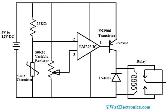
A simple heat sensor switch circuit with LM393 comparator IC is shown below. The LM393 IC used in this circuit is a dual voltage comparator including several features such as wide operating voltage ranges from 2V to 36V DC, high gain, wide bandwidth, low power consumption, etc. At the output of this circuit, a relay switch is used so that any AC/DC equipment can be connected which is operated and controlled at the desired temperature.
The required components to make this circuit mainly include; a 5V to 12V DC Input Supply, LM393 IC, 2N3906 transistor, 50KΩ Thermistor, 22KΩ resistor, 50KΩ variable resistor, relay, and 1N4007 Diode.

Heat Sensor Switch with LM393 IC
Working
This heat sensor switch circuit operates with 5V to 12V DC. A thermistor in this circuit can be used to detect the heat. Here the resistance of this thermistor is inversely proportional to the temperature around it. Whenever the heat rises above the preset level the thermistor’s resistance will be completely reduced & it allows the flow of current throughout this circuit.
The comparator IC will be turned ON and it will turn ON the transistor which acts as a switch for the relay. Any load can be activated to this relay so that it will be activated. The relay in this circuit should have an equal voltage as compared to the operating voltage.
Here 50K variable resistor is used to adjust the sensitivity (or) the desired range of temperature at which point you desire the circuit to trigger. This heat sensor switch circuit is used in lights, fans, lamps, heat sensing alarms, electronic devices, fire alarms, etc.
Applications
The applications of LM393 comparator IC include the following.
- The LM393 comparator IC drives different loads like motors, lamps, relays, etc.
- This IC is used in Zero-Crossing detectors, Voltage Comparator circuits, High Voltage protection/Warning, Oscillator circuits, and battery-powered Applications.
- These are used in comparator circuits, voltage detection, ADC, peak voltage detectors, time-delay generators, oscillator circuits, etc.
- These comparator ICs are used in oscillators, logic systems, and battery-powered applications.
Please refer to this link for the LM393 Comparator IC Datasheet.
Thus, this is an overview of the LM393 comparator IC, pinout, specifications, circuit, working, and its applications. The LM393 IC is an independent precision voltage comparator that is capable of operating with single (or) split supply operation. This IC has a 2.0 mV input offset voltage so this IC best choice for applications in automotive, industrial electronics, and consumer. Here is a question for you, what is LM2903 IC?