The Filter Capacitor is a basic type of capacitor. It is designed in such a way that, it can prevent a certain range of frequency signals to enter another circuit. It is mostly preferred during the filtering of the low-frequency signals. A capacitor is generally used as a parallel plate capacitor. In this case, the capacitor is connected to the respective circuit so that the desired signals are filtered and excess signals are eliminated from the circuit. This type of capacitor has many applications in the suppression of the signals, in the circuits designed for glitch removal, etc.
What is a Filter Capacitor?
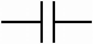
Definition: A capacitor that is introduced to filter the certain desired frequency signals can be defined as a filter capacitor. A filter capacitor can be designed to pass low-frequency signals or high-frequency signals or even a certain brand of signals are also filtered with these types of capacitors. The filter capacitor symbol is shown below.
It is generally a basic parallel plate capacitor. But its connection concerning the circuit makes it different. Sometimes a ceramic capacitor is also preferred for the limiting of the signals.

Filter Capacitor Symbol
Filter Capacitor Working
This capacitor works on the principle called capacitive reactance. The meaning of capacitive reactance is that the impedance value of the particular capacitor changes based on the frequency signals passing through the respective capacitor. Let us consider the example of the resistor in the circuit. The resistance of the device cannot vary it is offering the same resistance based on its fixed value. But capacitor has variable capacitance. The capacitance is affected because of the applied frequency value of the signals.
Hence these devices are referred to as reactive ones. The impedance value is altered because of this type of capacitor’s involvement in the circuit. If the value of the frequency signals is high then, in that case, the resistance offered by that particular capacitor is low and vice-versa. Hence this indicates that the resistance and the frequency of the signals are inversely related to each other.
Formula
The filter capacitor formula can be derived based on the cutoff frequency selected for the filtering and the impedance varying concerning the frequency of the signals.
X c = 1/2* 3.14* f c
The above formula shows the inverse relation of the cut-off frequency of the respective circuit with the respective impedance variation in the circuit.
Filter Capacitor Circuit to Block DC and Pass AC
As already discussed it offers low resistance concerning the high-frequency signals and high resistance concerning the low-frequency signals. To block DC we need to prefer high-frequency signals to be transmitted. In this case, the designed circuit acts as a high pass filter.
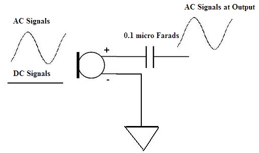
But in certain cases, a circuit requires both the signals that are DC and AC. The best example, in this case, is the use of a microphone. This requires the initial current as DC to start the circuit. After that, the AC signals are transmitted and received at the output. Approximately a 0.1 microfarads value of the capacitor is chosen in the circuit so that it can block the DC value and the AC signals are passed through the circuit.

Filter Capacitor Circuit to Block DC and pass AC
Applications
This type of capacitor is very advantageous in various circuits. Some of the applications of the filter capacitor are listed below:
- In the design of high pass filters, low pass filters, etc…that are analog filters
- Line filters, which are present in the sets of television so that the flicking of images can be avoided.
- As the protective circuits where the concern is about heavy loads such as air conditioners, refrigerators, etc…
- Mainly these are preferred in the processing of signals.
In this way, the filter capacitor has many applications in various fields. Let us see the importance of the capacitor filter in the bridge rectifier circuit.
Please refer to this link to know more about Matched Filter MCQs, Capacitors MCQs
Bridge Rectifier
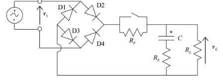
Generally, a full-wave rectifier can be drawn to obtain the smoothening value of the Dc as output in comparison with the output of the half-wave rectifier. But still, the output of this rectifier obtained is consists of certain ripples in the circuit. Hence to eliminate these ripples a filter circuit is connected to the bridge rectifier. This helps in obtaining the resultant output in its pure DC form.

Bridge Wave Rectifier with Capacitor Filter
The pulsating Ac that is unwanted signals can be eliminated with the help of capacitors. Hence capacitor filter has many applications. It can be of eliminating ripples from the circuit. Now can you describe what should be the approximate capacitance value in the microphones?