An NPN Transistor is a type of three-terminal bipolar junction transistor (BJT) that is formed with one p-type semiconductor material by sandwiching in between two N-type semiconductor materials. In this type of transistor, the majority of charge carriers are electrons and the minority charge carriers are holes. The main function of this NPN transistor is to amplify the weak signal that is entering the base terminal & generate strong signals at the collector terminals. The direction of electron movement in this type of transistor is from the emitter terminal to the collector due to which the flow of current constitutes within the transistor. There are different types of NPN transistors available from different manufacturers. Among them, the 2N2219 transistor is one of the types of NPN transistor. This article provides brief information on the 2N2219 NPN transistor.
What is a 2N2219 NPN Transistor?
The 2N2219 transistor is a small signal transistor, used commonly in amplifying & switching circuits. This NPN transistor is very similar to the NPN 2N2222 transistor except it comes within a metal can package & also operates on slightly higher voltages as compared to 2N2222. In the 2N2219 NPN transistor, the collector & emitter terminals will be reverse biased while the base terminal is held at GND & the collector & emitter terminals will be forward biased whenever a signal is given to the base terminal.
Working
This 2N2219 NPN transistor is biased whenever little voltage is provided to the base pin of this transistor, so the base current must be restricted to 5mAmps. Once this NPN transistor is completely biased, then it allows 800mA of maximum current to supply across the emitter & collector terminals, known as the saturation region. Once the base current is detached this NPN transistor will become completely off, then this region is known as the Cut-off Region & the voltage at the Base Emitter could be approximately 600 mV.
Pin Configuration:
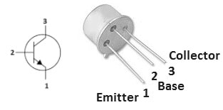
The pin configuration of the 2N2219 NPN transistor is shown below. This transistor includes three terminals which are discussed below.

2N2219 NPN Transistor PinOut
Pin1 (Emitter): The flow of current drains out throughout this terminal and is connected to GND normally.
Pin2 (Base): This terminal controls the transistor biasing, so this terminal turns ON/OFF the transistor.
Pin3 (Collector): This terminal allows the flow of current and is connected normally to a load.
2N2219 NPN Transistor Features & Specifications:
The features and specifications of the 2N2219 NPN transistor include the following.
- It is a small signal NPN transistor.
- 2N2219 NPN transistor is available in TO-39 package/case.
- Its operating temperature ranges from -65°C to 150°C
- This transistor includes 3 pins.
- Its polarity is NPN.
- Its maximum collector current is 800mA.
- Its transition frequency is 250MHz.
- Its emitter to base voltage or VEB is 5V.
- Its minimum DC current gain (hFE) is 30.
- Mount is Through Hole.
- Its maximum power dissipation is 800mWatts.
- Its breakdown voltage from collector to emitter is 30V.
- Its saturation voltage from the collector to the emitter terminal is 1.6 volts.
- Its collector-to-base voltage is 60 volts.
- Its Turn-on and Turn-off time is 40ns & 250ns.
- Alternative 2N2219 NPN transistors are; BC636, BC549, BC639, 2N2369, BC547, 2N3055, 2N3906, 2N3904, 2N5551 and 2SC5200. Equivalent 2N2219 transistors are; 2N5551, NTE123, 2N2218, 2N3109, 2N4403 & 2N3107 because the electrical specifications of these types of transistors are nearly the same.
NiCd Battery Charger Circuit
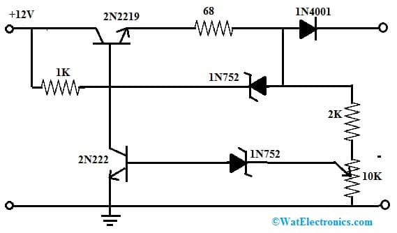
A simple Ni Cad 12V battery charger circuit is shown below. The simple charger circuit is connected as a constant current source. This charger circuit possesses extremely low internal resistance so that the output current is large comparatively upto 74mAmps. So, this battery charging circuit will be turned off automatically whenever the battery is charged completely.
The required components to make this NiCd battery charger circuit mainly include; a 12V NiCd battery, 2N2219 transistor, 5.6V 1N752 zener diodes, 1N4001 diode, 2N222 transistor, 10K potentiometer, resistors 68 ohms, 2K and 1K. Connect the circuit as per the below circuit shown below.

NiCd Battery Charger Circuit
Working
This simple NiCd battery charger circuit is still required because some applications that demand high current depend on NiCd. This type is still better in terms of low cost & high output current. This simple battery charger circuit is mainly used for charging a 12Volts NiCd battery at approximately 74 mA until this battery is charged completely. This simple circuit requires around 4 hour’s time to recharge a totally dead or empty battery based on the capacity of the battery.
Basically, this battery charger circuit works like a current source with the auto cut-off feature. The current regulation in this circuit can be done by simply maintaining a fixed voltage across a 68-ohms resistor at the emitter terminal of the 2N2219 transistor. So this fixed voltage can be stabilized through a 1N752 zener diode where this diode maintains the voltage at a 68-ohm resistor at approximately 5Volts and provides a constant 74 mA of current.
The auto-off feature in this circuit simply works by checking the o/p voltage before the 1N4001 diode relative to GND, because this voltage enhances in accordance with the voltage of the battery which is charged.
Once the voltage of the battery reaches the complete-charging level, the lower side 1N752 zener diode will supply the current to trigger the 2N222 transistor and it shorts the base terminal of the higher side transistor and turns off the process of charging. To calibrate the shut-off point, connect a 270-ohm 2-watt resistor to connect across the charge terminal & regulate the potentiometer until the voltage level of the charging terminal shows 15.5V.
Characteristics
2N2219 NPN Transistor characteristics are discussed below.
- These transistors are bipolar junction transistors which means these transistors have a structure with three regions of alternating N-type & P-type semiconductors.
- NPN transistors are designed mainly to amplify electrical current, so used in a wide range of electronic applications such as switches, oscillators & amplifiers.
- In order to work 2N2219 NPN transistors, the junction of the base-emitter of this transistor should be forward-biased, which means the base terminal should be connected to a +ve voltage relative to the emitter terminal.
- The input impedance of these transistors is high, so they draw less current from the i/p source and cause a voltage drop across the source.
- These transistors generate an inverted o/p which is relative to their i/p.
Interfacing 2N2219 NPN transistor to a Microcontroller:
When interfacing a 2N2219 NPN transistor to a microcontroller, you generally use the transistor as a switch to control higher power devices (like a motor, relay, or a high-power LED) with a low-power microcontroller pin. Below is a simplified example of how you might connect a 2N2219 transistor to a microcontroller.
Connections:
- Collector (C): Connect this to the positive supply voltage (Vcc) through the load (e.g., a motor or relay coil).
- Base (B): Connect this to a microcontroller pin through a current-limiting resistor (RB).
- Emitter (E): Connect this to the ground (GND) of your system.
Resistor Value Calculation:
You need to calculate the value of the base resistor (RB) to limit the current flowing into the base of the transistor. The formula for the base current (Ib) is given by
IB= (VMCU−VBE )/RB
Where:
- VMCU – is the voltage supplied by the microcontroller pin (usually 5V for most microcontrollers).
- VBE – is the base-emitter voltage drop of the transistor (approximately 0.7V for silicon transistors like 2N2219).
- RB – is the base resistor.
Choose a standard resistor value close to the calculated value.
Example Code:
Let’s assume it is connected to a AVR microcontroller. Configure one of the pin as an output pin and set the Port to high to turn ON the transistor and OFF to turn off the transistor..
#include <avr/io.h> // Assuming you’re using AVR microcontroller
#define TRAN_PIN PB0 // Assuming the pin is connected to PB0
void init() {
DDRB |= (1 << TRAN_PIN); // Set TRAN_PIN as an output
}
void turnOnTransistor() {
PORTB |= (1 << TRAN_PIN); // Set TRAN_PIN high to turn on the transistor
}
void turnOffTransistor() {
PORTB &= ~(1 << TRAN_PIN); // Set TRAN_PIN low to turn off the transistor
}
int main() {
init();
while (1) {
turnOnTransistor();
// Do something, e.g., wait for a while
_delay_ms(1000);
turnOffTransistor();
// Do something else, e.g., wait for a while
_delay_ms(1000);
}
return 0;
}
It is also important to know on few precaution to be considered before connecting a microcontroller to a transistor. Click on the the link to know it.
Advantages
The advantages of the 2N2219 NPN transistor include the following.
- These transistors are preferred mostly as compared to PNP because of faster electron mobility.
- These transistors are most appropriate for negative ground systems.
- This transistor operates at higher voltages.
- This NPN transistor is a low-power signal transistor.
- These are very efficient transistors as compared with the 2N222 transistor.
- This transistor uses 10 to 20 microamps of less current for controlling a higher flow of current throughout the base and emitter terminals.
2N2219 NPN Transistor Applications
The applications of the 2N2219 NPN transistor include the following.
- 2N2219 NPN transistor is used mainly for switching & small signal general-purpose amplification applications.
- This transistor is used in different driver modules like LED driver, relay driver, and many more.
- This transistor is used in the configurations of the Darlington pair.
- This NPN transistor is used in amplifier modules which include; audio amplifiers, signal amplifiers, power amplifiers, etc.
- This transistor exhibits low voltage & high current, so it is an ideal choice, especially for high-speed switching.
- This transistor is used for switching and amplifying devices.
- This transistor can also be used in DIY kits and electronic projects.
- The 2N2219 medium power-based NPN transistor is mainly used for amplifier circuits and driver applications
- It is used in DC & VHF or UHF amplification.
Please refer to this for How to Select a Transistor.
Please refer to this link for the 2N2219 NPN Transistor Datasheet.
Thus, this is an overview of the 2N2219 NPN Transistor, pin configuration, specifications, circuit, working, characteristics, advantages, and applications. The 2N2219 NPN transistor is available in TO-39 & TO-5 packages because both of these packages are similar & also powerful. These packages are made through metal CAN and are extremely good at power dissipation & heat resistance. This 2N2219 NPN transistor is a medium-power transistor, used mainly for driver applications & amplifier circuits. Here is a question for you, what is 2N222 transistor?