Hall Effect is a technique of the measurement of the voltage that is transverse. It was proposed by Edwin Hall in the year 1879. The purpose of this effect is to study the behavior of the current carried in the respective conductors present in the circuits. It is also used in various application sensors such as pressure sensors, current sensors, etc… For the measurement of the intensity of the magnetic field in the circuit, hall effect sensors are utilized. The measurement of this magnetic field results in the study of the current in the conductor.
What is Hall Effect?
The current flow in the conductor results in the generation of the transverse force on the moving carriers that possess certain charges. Once the force is applied, the buildup is formed across the sides of the conductor. Hence, it results in the generation of the voltage. This effect is known as the Hall Effect because this voltage is responsible for the study of the current evolved in the conductors. This effect can be measured with the kind of sensors known as Hall Effect sensors.
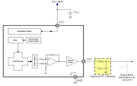
Hall Effect Sensor
These sensors are utilized in the measurement of the magnitude of the intensity of the magnetic field. Once the magnetic field is detected in the circuit, a voltage is generated. This voltage is referred to as Hall Voltage. This voltage is responsible for the detection of the density of magnetic flux. These sensors are generally acting as linear transducers.
Working Principle
The principle involved in the Hall Effect sensor is similar to that of the hall voltage. Let us consider a conductor with a thin strip and it is provided with the electric supply. Once the current is provided to the conductor, the charge flows in a straight direction in a line that is perpendicular to the direction of the magnetic field of the conductor. In this way, some carriers like electrons will be gathered at one side of the field.

Hall Effect Sensor
Now the conductor plane is partitioned in two ways. One side acts as positively charged and the other as negatively charged. Because of this difference in the potential, the voltage gets generated. This is referred to as the Hall voltage. Until the balance is obtained, the charge carriers tend to move from one side to another. This changes the value of the magnetic flux. Once the separation in the conductor stops the density value of the magnetic flux is obtained. In this way, the Hall Effect sensor works.
Experiment
Now let us discuss the hall effect experiment.
Aim: To determine the value of the hall voltage.
Apparatus Required
- Two solenoids.
- Constant current supply.
- Four probes.
- Digital Gauss meters.
- Hall Effect Apparatus with the constant current generator (CCG), Probes, and the Digital Voltmeter.
Theory
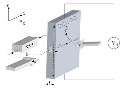
When the current supply is provided to the conducting material and it is placed in between the solenoids that are present in the perpendicular direction of the magnetic fields. The voltage is generated because of the potential difference across the sides of the material. This voltage is known as the Hall voltage. This voltage is responsible to determine the type of material.

Hall Effect in Conductor
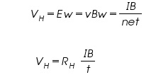
The equation that determines the hall voltage is

Where ‘I’ is current, ‘B’ represents the magnetic field and ‘t’ denotes the thickness of the material.


Here R H represents the coefficient of the Hall voltage.
Please refer to this link for Hall Effect MCQs
Procedure
- Establish the connection between the current source which is constant with the solenoids.
- The set of four probes is provided the connection with the gaussmeter and kept in between the solenoids.
- Switch ON the meter and the current source.
- Varying the current present in the solenoids with a certain fixed amount of intervals of current through certain values. With the gaussmeter, the readings are noted.
- Then OFF the switch of the meter and the source of the current. Then knob is turned towards the minimum value of the current.
- Hall probe is fixed on the stand of wood. Then pair of wires that are available in green color are connected to CCG. The remaining pair of red wires are connected to the voltmeter in the apparatus of the Hall.
- Replace the probes with the apparatus probes. Keep the material required to be identified between the terminals of the solenoids.
- Then switch on the respective connected devices.
- Increase the value of the current from CCG. To the present magnetic field measure the different values of the Hall Voltage.
- The thickness of the placed sample can be measured by the apparatus called screw-gauge.
- Then calculate the coefficient of the hall and the concentration of the carrier.
Results
- To determine the value of the Hall Voltage = ________.
- Coefficient of the Hall of the placed material = _________.
Hall Effect Applications
There are various applications of the Hall Effect. Some of them are listed as follows:
- The probes that are present in the Hall devices are utilized in magnetometers.
- The devices that perform Hall Effect is immune from the dust, dirt, etc… hence these devices can be used as the sensing elements of the position, in another electronic sensing.
- It is very helpful in sensing the magnetic field for industrial applications.
- The sensor that possesses Hall Effect can be used in automobiles for the detection of fuel levels.
- These effect sensors are useful in digital electronics.
In this way, there are various applications involved in the device that performs the Hall Effect.
Generally, there exist two types of sensors based on the relation that exists between the density of the magnetic flux and the hall voltage, they are linear and threshold sensors. In these sensors, if the relation between the magnetic flux and the voltage generated at the output is linear, then the sensors are defined as linear sensors. But in the threshold sensors, for each value of the density of magnetic flux, there observed a decrease in the voltage generated at the output. Now can you describe which type of sensor is most widely preferred for digital electronic applications?