A semiconductor device that is used to switch or amplify electronic signals is known as a transistor whereas a power transistor is a type of transistor particularly designed to be used in high-power-based applications. As compared to normal transistors, these transistors are normally designed to be used in high-power applications like power amplifiers, high-power devices, DC-to-DC converters, etc. These transistors are made with silicon (Si) and are normally larger & robust. This article discusses an overview of a power transistor, its working, and its applications.
What is Power Transistor?
A type of transistor that is used where high power is being utilized like high-power amplifiers & power supplies is called a power transistor. This transistor handles with high power, so used in switching & audio circuits. This transistor with three terminals is mainly designed with a semiconductor material to connect with an external circuit. Whenever voltage (or) current is supplied to one pair of transistor terminals, then the current flow can be controlled in another pair of transistor terminals because of the higher output power as compared to the input power.
Pin Configuration:
The power transistor pin configuration with its symbol is shown below. This transistor is available with three terminals; base, emitter & collector.
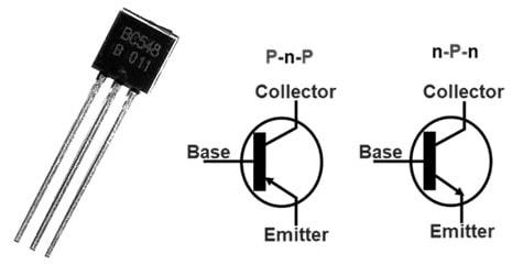
Power Transistor Symbol
- Pin1 (Base Terminal): This terminal helps in biasing of transistor by turning ON/OFF this transistor
- Pin2 (Collector Terminal): The current supplies through this terminal and it is connected normally to load.
- Pin3 (Emitter): This terminal is used to drain out the flow of current and it is connected simply to the ground terminal.
Features & Specifications:
The features and specifications of the power transistor include the following.
- This transistor includes three terminals.
- It uses advanced process technology.
- The error voltage of this transistor is less
- It has a very fast switching speed.
- Its operation is full-voltage based.
- This transistor works with high current & power
- These transistors’s size is large.
- These are used in high-power applications.
- Its continuous collector current is 3A.
- Its collector-to-emitter voltage is 50 Volts.
- Its collector-to-base voltage is 50 Volts.
- Its emitter to base voltage is 4Volts.
The examples of NPN power transistors are; 2SE5200, TTC5200, 2SA1962, KTA1962A, 2SA2151A-O, 2SA2151A-Y, KTA1943, 2SA2151A-P, KTA1943, KTA1943A, FJA4213, KTA1962, FJL4215, MJW1302/MJW1302AG. The examples of PNP power transistors are; MJD350, TTA1943, TIP32, 2N5194G, 2SA1943, 2N5195G, etc.
Power Transistor Structure
A power transistor is composed of semiconductor materials. This transistor includes three terminals; base, emitter, and collector. These transistors can be either PNP or NPN polarity. In the NPN power transistor, the p-type semiconductor is sandwiched between two N-type semiconductors. In contrast, in a PNP power transistor, the n-type semiconductor is sandwiched between two P-type semiconductors. This transistor has a fairly large cross-section area that contains alternate P & N-type layers that are connected together.
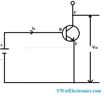
NPN Power Transistor Configuration
Power Transistor Working
The NPN power transistor configuration is shown above. This transistor works whenever a voltage (or) current is provided to one of the transistor terminals then it controls the voltage (or) current at the other pair of terminals.
The power transistor works in four regions based on the forward & reverse biasing conditions like Cut off, Active, Quasi saturation, and hard saturation regions. Whenever the NPN power transistor is connected in reverse bias condition then this transistor enters into a cut-off region. Once the collector-to-base region of this transistor is reverse biased & base to emitter is forward biased, then the transistor will be in an inactive region. In this region, when the base current increases, then the collector current also increases.
When this transistor is in the quasi saturation region, then the collector to base & base to emitter is connected in forward bias condition. When the collector to base & base to emitter terminals are connected in forward bias condition then hard saturation region is achieved
Power Transistor Types
These transistors are available in different types like BJTs, MOSFETS, SITs, and IGBTs.
BJTs or Bipolar Junction Transistors
A power BJT is a three-terminal semiconductor device with two p-n junctions that are capable of amplifying or magnifying a signal. The terminals of this transistor are; the base, the emitter & the collector. These transistors are available in two types; PNP and NPN depending on the doping types of terminals. PNP transistor includes two semiconductor junctions that have a thin n-doped cathode region whereas NPN transistor includes two semiconductor junctions that contain a thin p-doped anode region.
The charge flow within this transistor is because of the charge carrier’s diffusion between the two regions. In BJT, the emitter region is doped highly as compared to the base and collector regions. These two regions have similar charge carrier concentrations. These transistors are used in different electronic devices like televisions, mobile phones, industrial control & radio transmitters. Please refer to this link for Bipolar Junction Transistor.
The characteristics of BJTs include the following.
- BJTs are available in large size, so allows maximum cur flow of current.
- These transistors have maximum breakdown voltage, high handling capacity & current-carrying capability.
- These are used in high-power applications.
MOSFETs
MOSFET is a kind of field effect transistor including three terminals; source, base & drain with an MOS structure. The main function of MOSFET mainly depends on the channel’s width. If the channel width of MOSFET is wide, then it works with high efficiency. In MOSFET, current conduction can be controlled between drain & source terminals by applying a voltage supply to the gate terminal. MOSFETs are available in different types like P-channel depletion, p- p-channel enhancement type, N-channel depletion, and n-channel enhancement type.
MOSFETs are mainly used for amplifying or switching signals. The capacity to adjust conductivity through the amount of voltage applied can be used to amplify or switch electronic signals. At present, these transistors are more commonly used as compared to bipolar junction transistors within analog and digital circuits. Please refer to this link for MOSFETs.
The MOSFET characteristics include the following.
- MOSFET is a voltage controller and it doesn’t require input current.
- This transistor provides a high i/p impedance.
SITs
Static induction transistor or SIT is a power transistor that includes three terminals. As compared to FETs, static induction transistors offer high voltage breakdowns. This kind of transistor has high frequency & high power with short multichannel. As compared to FETs, these transistors get higher breakdown voltages.
The characteristics of SITs include the following.
- The length of the channel is short.
- Its noise and distortion are less.
- It provides low terminal resistance.
- It has less gate series resistance and less capacitance from gate to source.
- It has less thermal resistance.
- It has a maximum capacity of audio frequency power.
- Its short turn-on & off time is normally 0.25 μs
IGBTs
IGBT or Insulated Gate Bipolar Transistor is a three-terminal semiconductor device composed of semiconductor material. These types of power transistors are mainly used for the purpose of switching. IGBTs include four alternating layers like P-N-P-N which are simply controlled by a MOS gate structure. The applications of IGBT are; AC and DC motor drives, UPS systems, power supply relays, contactors & drivers for solenoids. Please refer to this link for IGBT.
The characteristics of IGBT include the following.
- The loss is insignificant at the input.
- Its power gain is high.
- Its efficiency is high.
- Its size & cost is low.
- It has fewer switching losses.
Power Supply Circuit with TIP2955 Power Transistor
The power supply circuit using the TIP2955 power transistor is shown below. This circuit is used to obtain 5V DC from a 110V AC or 230V. The required components to make this circuit mainly include; LM7805 IC, TIP2955 transistor, 10A bridge rectifier diode, 230 to 12V, 5A transformer, 10uF and 3300uF electrolytic capacitor, 0.33uF ceramic capacitor, and 1K resistor. Connect the circuit as per the circuit shown below.
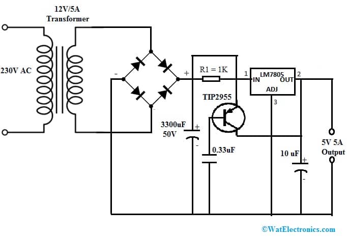
Power Supply Circuit with TIP2955
Working
The power transistor used in this power supply circuit is TIP2955. This is a PNP Si epitaxial-base planar power transistor that is available in a TO-218 plastic package. This transistor is mainly used in series regulators, shunt regulators, power switching circuits, hi-fi amplifiers, etc.
In the above power supply circuit, the 230V AC supply is first stepped down into 12V AC. This stepped-down voltage can be supplied throughout a bridge rectifier. Here, the 12V DC is filtered with a capacitor & is connected to the LM7805 regulator. The TIP2955 transistor in this circuit works as a switch. Since we require the LM7805 regulator to work as a fixed 5Volts supply, the Adj pin of the regulator is connected to the GND terminal. The capacitors like 0.33uF & 10uF are required for smoothing the spikes of current. Now the output 5V / 5A is ready to be used in different applications.
This simple circuit is used as a general-purpose power supply. This circuit is used to design a plug-and-play display device with inbuilt memory used for images. This power supply circuit can also be used to power up home automation boards in the switchboard.
Power Transistor Characteristics
The power transistor operates in three regions; active, cut-off, and saturation.
- The power transistor will have a base current in the active region, thus, the collector current will raise proportionally through gain Ic = β.Ib.
- The base current is ‘0’ in the cutoff region, thus the device acts as an open switch.
- The base current of the transistor is maximum in the saturation region. So the device acts as a closed switch.
Input Characteristics
The input characteristics of the power transistor are drawn in between IE and VBE by maintaining VCE stable. At the base-emitter (BE) junction, it acts like a diode. The input characteristics of this transistor look like the PN junction forward bias characteristic curve. For the various VCE values, the transistor’s breakdown curve changes proportionately.
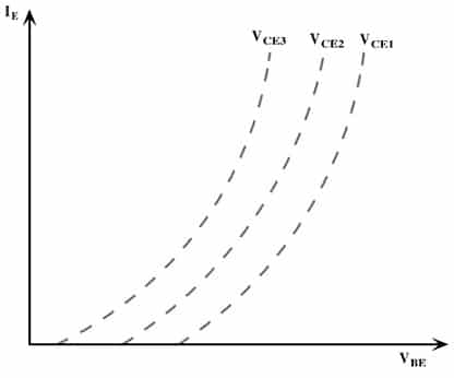
Input Characteristics
Output Characteristics
The output characteristics of the power transistor are drawn between VCE versus IC by maintaining various base currents. Here, the base current is enhanced from ‘0’ to max. The output characteristics of the power transistor have mainly three regions which are discussed below.
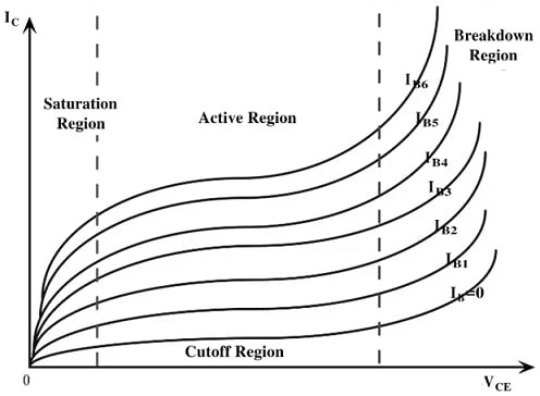
Output Characteristics
Cut-Off Region
When the base current is ‘0’, then the collector current is small & the transistor will be forced into the cutoff region. In this region, the transistor will be in off condition, so it operates an open switch. Currently, junctions like base to emitter & collector to base are reverse-biased. So in this region, the collector-to-emitter voltage is equivalent to the voltage supply & the circuit current will be zero.
Active Region
In the active region, the transistor base-emitter (BE) junction is forward-biased whereas the collector-base (CB) junction is reverse-biased when a different base current is provided. The transistor in this region acts as the amplifier.
Saturation Region
When the base current of the transistor is maximum, it enters into the saturation region. The transistor acts as a closed switch when it is saturated due to both junctions being forward-biased.
Advantages & Disadvantages
The advantages of a power transistor include the following.
- The power transistor operates at switching frequencies which range from 10 – 15 kHz.
- The voltage gain of this transistor is high.
- The current density of the transistor is high.
- The forward voltage of this transistor is low
- These transistors carry large currents in ON condition & block extremely high voltage within OFF condition.
- This transistor is very simple to turn ON & OFF.
- The bandwidth gain is large for this transistor.
- The ON state voltage drop is low across the transistor
- It controls power which is delivered to the connected load, choppers & inverters.
The power transistor disadvantages are discussed below.
- The power transistor has high noise.
- The thermal stability of this transistor is low.
- The reverse blocking capability of this transistor is extremely low.
- This transistor can be broken because of the second breakdown or thermal runaway.
- This transistor needs more complex drive & control circuits.
- These transistors have lower efficiency.
- These are larger & heavier.
- These are normally more expensive
- The switching speed of this transistor is slower.
- These transistors can generate heat once they operate which can harm the transistor.
- These transistors have the highest voltage & current ratings.
Where to use/Applications
The applications of the power transistor include the following.
- Power transistors are used to design amplifiers.
- These are used within Stereo systems, audio frequency amplifiers, and AF/RF circuits.
- These transistors are used in low slew rate devices, circuits based on push-pull configuration, and switching circuits wherever a high current is required.
- This transistor is used as an intermediate Power switch & medium power switch.
- These are used in relays, converters, SMPS, power amplifiers, power supply, DC/AC converters, inverters, and power control circuits.
- These transistors are used as a power amplifier for power amplification within electronic devices.
- It is used within power control circuits, audio devices, signal amplifier devices, as a switch within analog & digital circuits.
- This transistor is used within the power regulator & controller.
- It is used in current electronic ICs & in cellular phones.
- These are used in microprocessors.
- These transistors are used in motor control circuits to control the motor’s speed & direction.
- These are utilized mainly to switch the flow of current throughout the windings of the motor so that it controls the motor’s rotation.
- These transistors are used in robotics, electric vehicles & industrial machines.
- These are utilized to drive the audio speakers, which change the signal from electrical to sound. These types of transistors are used in car audio systems, professional audio equipment & home theater systems.
Thus, this is an overview of the power transistor – working, structure, types, application circuits, advantages, disadvantages, and applications. This transistor is used in amplifying & switching electronic signals & power. These transistors are used in high-power amplifiers & power supply systems. Here is a question for you, what is FET?