In the industrial sector, temperature sensing using temperature sensors is the most sensitive parameter in many cases like in a reactor, electrical machine winding, etc. These sensors are mainly connected to devices to measure temperature very efficiently & accurately in a specific time & change it into an electrical signal. There are different types of temperature sensors like NTC thermistors, RTDs, thermocouples, and semiconductor-based sensors. This article provides brief information on an RTD sensor or resistance temperature detector sensor.
What is an RTD Sensor?
A type of temperature sensor that has a resistor, used to change the value of resistance when its temperature changes is called an RTD sensor or resistance temperature detector. As compared to other types of temperature sensors, this sensor is very accurate & also stable. The most frequently used RTD sensor is Pt100.
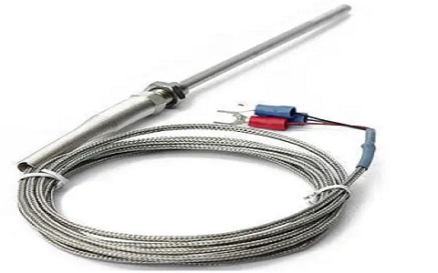
RTD Sensor
Generally, resistance temperature detectors have either platinum/copper or nickel wires because the temperature coefficient of these materials is positive. Many RTD elements are designed with a fine wire that is covered around a glass or ceramic-made core. Usually, the element is quite fragile, thus it is frequently located in a sheathed probe to defend it. RTDs replace thermocouples due to repeatability & higher accuracy within industrial applications under 600 °C.
RTD Sensor Working Principle
RTD sensor works on the basic relationship between metals & temperature. When the temperature of the resistance element of RTD increases, then electrical resistance also increases. So, RTD elements are normally specified based on their resistance value at 0 degrees Celsius. The specification of the most common RTD sensor is 100 Ω which means the element of RTD shows 100 Ω of resistance at 0°C. For RTD elements, the most popular Platinum metal is used due to its chemical inertness & almost the relationship of linear temperature vs. resistance. Other metals are used not frequently because the resistor elements have copper, Balco & nickel.
The RTD is more accurate if it has more wires. Generally, different RTDs use 2-wire, 3-wire, or 4-wire measuring systems based on the preferred level of accuracy & cost. All wire measuring systems’ RTD is ultimately connected to a bridge circuit to produce a voltage signal.
Features and Specifications
The features and specifications of the RTD sensor include the following.
- RTD is a resistance temperature detector.
- Temperature range is from -200°C – 850°C
- The range of resistance is from 1.849K – 39.026K.
- Its accuracy is ±0.1°C.
- Its nominal resistance at 0°C is 100Ω.
- Wiring configuration is two, three, or four-wire.
- Alternative temperature sensors are; Thermocouple, DHT11, LM35, LM75, DHT22, TMP100, DS18820, LM35DZ, SHT15, D6T & TPA81.
Components
The RTD sensor includes different components like sensing element, protecting tube, process connection, wire configuration, and cold end termination which are discussed below.
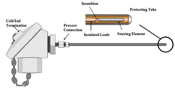
RTD Sensor Components
- The sensing element of this sensor is the metal element for sensing actual temperature.
- The protecting tube is made with stainless steel which helps in protecting the sensing element from the humidity & external environment.
- Process connection contains the standard fitting.
- RTD sensor wire connection is available in different configurations like two-wire, three-wire, & four-wire but the most frequently used configuration is a three-wire and is extensively used in industrial applications.
- The cold end termination of the RTD sensor is used to terminate through the controller like PID, Closed-loop, PLC, and many more.
Types of RTD Sensor
RTD sensors are commonly available in different types which are discussed below.
Wire-Wound RTDs
Wire-wound RTDs are the most precise type of temperature sensor. The sensing element in this type of sensor is comprised of an ultra-thin and small coil of wire and it can be wrapped up in a glass tube or ceramic. The sensing elements of this sensor can be made easily into Pt100 probes by simply mounting them in sheaths or metal tubes. So this guards them from their surroundings and improves their durability.
These types of RTDs are more accurate. RTD sensors with glass cores can be immersed within various liquids whereas RTDs with ceramic cores can be utilized to measure very high temperatures accurately. But, they are very costly compared to thin-film type RTDs.
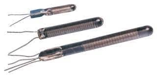
Wire Wound RTD
Thin-Film RTDs
Thin film RTDs are very popular due to their reliability, low cost & ruggedness. Thin-film elements of this sensor are more resistant to damage from vibration or shock as compared to other types. Thin film elements of this sensor have a thin metal layer arranged on the ceramic material’s substrate. These RTDs provide substantial reduction during assembly time & it has the benefit of improved resistance for a specified size. Because of the manufacturing technology, the size of the device is small, which means it responds very fast. At present, these types of RTDs are less stable, although they are becoming very famous due to their advantages like production cost & size.
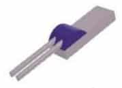
Thin Film RTD Sensor
Coiled RTD Sensor
This type of RTD sensor has a thin wound wire that is enclosed within a ceramic (or) glass housing filled by a non-conductive powder. Generally, the glass housing is placed into a protecting metal sheath. The resistance wire of this sensor is rolled into tiny coils, which freely fit into a ceramic shape after that filled with non-conductive powder. The resistance wire expands freely when the temperature changes & reduces errors caused by mechanical strain. The powder enhances the heat transfer speed into the coils, thus improving the response time. These RTDs are protected normally by a metal sheath to form RTD temperature probes.
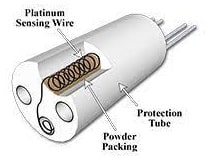
Coiled RTD Sensor
PT100 RTD Sensor
In the PT100 RTD sensor, the term ‘PT’ is a platinum element which means this sensor is made with a PT element whereas ‘100’ indicates the resistance factor. This sensor is most accurate including a 100 Ω resistance factor f at 0° C (or) 32° F with extremely small drift ultimately. These sensors have numerous versions with different temperature coefficients, signified by the Greek letter ‘α’.
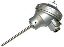
PT100 Sensor
PT1000 RTD Sensor
The PT1000 RTD sensor is made with platinum element and it has 1000 Ω of resistance factor. This type of RTD sensor is used in 2-wire applications. This sensor has exceptional resistance which is accurate extremely by small drift over time. These sensors have a high resistance value & need less current which are suitable for configurations that utilize less power. When the power consumption of this sensor is low, it generates low heat & has fewer errors which are caused by self-heating.
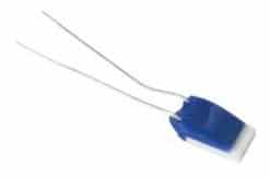
PT1000
Types of RTD Sensor Configurations
RTD sensors are available in three configurations 2-wire, 3-wire & 4-wire. There are some differences between these configurations which must be taken into consideration while choosing the suitable device for the application. By understanding these configurations, designers can ensure that this sensor can be used very efficiently.
2-wire RTD
The two-wire RTD configuration is a simple type of configuration as compared to others. In this configuration, a single lead wire is connected to every end of the element, and the resistance is calculated by simply measuring the resistance within the lead wires & connectors. This configuration results in some degree of error which is higher as compared to the actual measured temperature. So this can be avoided with calibration.
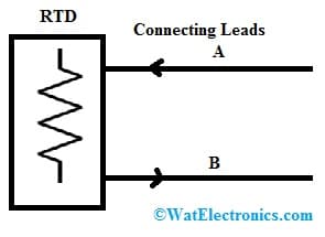
2-wire RTD
3-wire RTD
This type of configuration is used most frequently in industrial applications. In this configuration, 2-wires are connected simply to one sensor’s end denoted with A and B & to the monitoring device. The third wire like ‘C’ is connected simply to the element. The three wires in this configuration have equivalent lengths, thus their resistance is equivalent. This type of configuration also has some errors which can be adjusted through calibration.
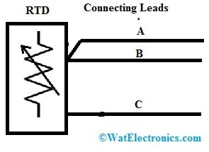
3-wire RTD
4-wire RTD
The 4-wire RTD configuration is time-consuming, expensive & the more complex configuration but it provides the most precise readings. In this configuration, DC current is supplied throughout two leads; A & C whereas the other two leads B & D are used to measure the voltage drop. If the current & voltage drop is known, then finding resistance is easy to read & the temperature across the system. This configuration is mainly used where high accuracy is required like; in laboratories & other settings.
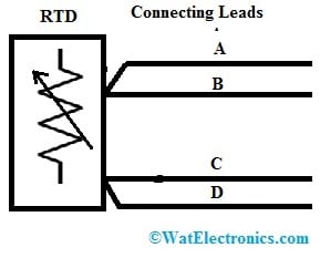
4-wire RTD
PT100 RTD Sensor Interfacing with Arduino Board
The PT100 RTD sensor interfacing with the Arduino board is shown below.
The required components to make this interfacing mainly include; a PT100 RTD sensor, 150Ω resistor, and Arduino Uno board. The connections of this interfacing follow as;
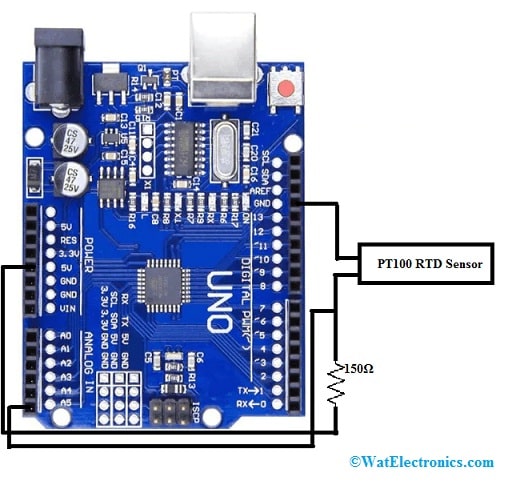
PT100 RTD Sensor Interfacing with Arduino Board
PT100 RTD sensor’s one end is connected to the Arduino board’s analog pin.
The same end of this sensor is connected to the 5V pin of the Arduino board through a 150Ω resistor. Here, the resistor is mainly connected to avoid heating issues.
Connect the PT100 RTD sensor’s other end to the GND pin of the Arduino board.
Once the connections are made, a logic program within the Arduino library is written based on the connection. After that, this program can be uploaded into the Arduino board using Arduino IDE software. Once the following Arduino program is uploaded, the temperature can be verified.
Code
#include <Wire.h>
const int analogInPin = A5; //sensor connected to A5 pin
const int SensorValueLow = 463;
const int SensorValueDiff = 36; // differance between high and low sensor value
const int TempValueDiff = 42; // differance between high and low Temp value
const int TempValueLow = 9;
int sensorValue = 0;
double Temp = 0;
void setup()
{
}
void loop()
{
sensorValue = analogRead(analogInPin);
Temp = sensorValue-SensorValueLow;
Temp = Temp/SensorValueDiff;
Temp = Temp*TempValueDiff;
Temp = Temp+TempValueLow;
Serial.print(sensorValue); //printing value of sensor on the serial monitor
Serial.print(Temp); // printing temperature on the serial monitor
delay(200); // interval of fetching data from sensor
}
By keeping the PT100 RTD sensor near to candle or ice cube material, you can observe the change in the readings of the temperature on the serial monitor.
Difference between RTD and Thermocouple
The differences between RTD and a thermocouple are discussed below.
| RTD Sensor | Thermocouple |
| RTD is used to measure a low range of temperature that ranges from -200°C to 500°C. | A thermocouple is used to measure a high range of temperature that ranges from -200°C to 500°C. |
| The operating principle of this sensor is; that when temperature changes then resistance will be changed. | The operating principle of this sensor is that temperature changes by change within generated emf. |
| It is expensive. | It is not expensive. |
| Its response time is 1 to 50secs. | Its response time is 0.1 to 10 seconds. |
| This sensor exhibits good stability. | This sensor has poor stability. |
| This sensor is more accurate. | Thermocouple sensor has poor accuracy. |
| RTD sensor is very sensitive, so small changes in temperature can be recognized. | This sensor has poor sensitivity responsive, so small changes in temperature cannot be recognized. |
| Its response time is not faster as compared to thermocouples. | Its response time is faster. |
| The physical size of RTD is large. | The physical size of the thermocouple is small. |
| Self-heating exists in this sensor. | Self-heating doesn’t exist in this sensor. |
| Its output is linear. | Its output is non-linear. |
How to Choose an RTD Sensor?
To select an RTD sensor, the different factors need to be considered.
- The type of sensing element is significant for the application of the sensor.
- The application of a sensor is another factor used to measure the temperature of either gas, solid, or liquid.
- Environmental conditions.
- The location of the RTD sensor like where it is mounted like handheld, wall-mounted, inside (or) outside, and many more.
- The operating range of the sensor means how much temperature it is going to measure.
- The connection of the sensor is another factor that means where you connect the feedback of the sensor & its wiring configuration.
Advantages & Disadvantages
The advantages of RTD sensors include the following.
- RTDs provide long-term stability
- This sensor has high repeatability.
- This sensor is appropriate for extreme atmospheres.
- These are very accurate & consistent.
- Recalibration is easy.
- These are easier to calibrate, maintain & install as compared to thermocouples, bimetal & digital thermometers.
The disadvantages of RTD sensors include the following.
- RTD sensitivity is low.
- It needs a 3-wire or 4-wire operation.
- These are expensive as compared to thermocouples.
- They can be affected by shock & vibration.
- The overall temperature range is smaller.
- It is less rugged within high-vibration environments
- These sensors need complex measurement circuit
- Self-heating & lead errors once high accuracy is required.
Applications
The applications of an RTD sensor include the following.
- The RTD sensor is used in communication & instrumentation as a temperature sensor & an amplifier.
- This sensor can work as an audio amplifier & also a temperature sensor of engine oil for automobiles.
- These sensors are applicable in computers, power electronics, consumer electronics, medical electronics, aerospace, military, handling & processing of food.
- RTD sensor helps in measuring temperature in industrial and laboratory processes due to their stability, repeatability, and accuracy.
- This sensor is used in computer, power electronics, consumer electronics, industrial electronics, aerospace, military, medical electronics, food processing & handling.
Please refer to this link for RTD Sensor MCQs.
Please refer to this link for the PT100 RTD Sensor Datasheet.
Thus, this is an overview of an RTD sensor, types, working, interfacing, configurations, differences, how to choose, advantages, disadvantages & its applications. An RTD (Resistance Temperature Detector) is a type of temperature sensor, used to measure temperature. When the metal temperature in this sensor increases, then resistance also increases. This sensor has high accuracy, repeatability & stability. Here is a question for you, what is an NTC thermistor?