A diode is a two-terminal semiconductor device. There are different kinds of diodes available in the market, but the zener diode is one type of diode used as crude voltage regulators or in protection circuits. It is very significant to keep in mind that a Zener diode is protected always with a resistor from a high current. This resistor is an ordinary resistor, used to limit the current that supplies throughout the Zener diode or throughout the load connected to the Zener diode. If the Zener diode is not connected to a resistor, the diode will get damaged because of the high current. This article discusses an overview of the 1N4733A zener diode, pin configuration, circuit, working, and its applications.
What is 1N4733A Zener Diode?
The 1N4733 is a Zener Diode with 1 Watt high-power 5.1V with a low reverse leakage current & precise working voltage. This Zener Diode is used in stabilizing & clipping circuits through high power rating. This diode is mainly designed for the stabilization of voltage. This diode is perfect to utilize in converter & power supplies circuits. 1n4733a zener diode allows the flow of current in two directions which means it conducts within both ways like forward & reverse. To conduct this diode in a reverse-biased state, reverse breakdown voltage should be attained.
The voltage drop across the diode doesn’t vary above a broad range of voltages, so it can be used for voltage regulation purposes. Not like normal diodes, these diodes simply work in breakdown regions & are most excellent for creating reference voltage.
This diode is available with an extremely doped PN junction & sealed glass package with different ratings of voltage that ranges from 3.3 – 91 V and it provides solid safety in all atmospheric conditions. This diode has dual slug construction and is corrosion-resistant. The two terminals of this diode are solderable very easily & can resist the highest temperature equal to 230 C.
Pin Configuration:
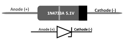
The pin configuration of the 1N4733A Zener Diode is shown below. This diode includes two terminals which are discussed below.

1N4733A Zener Diode Pin Configuration
- Pin1 (Anode): Current flows always throughout this terminal.
- Pin2 (Cathode): Current exists always from this terminal.
Features & Specifications:
The features and specifications of the 1N4733A zener diode include the following.
- Nominal zener voltage VZ is 5.1Volts.
- Power dissipation PZ is 1300mWatts.
- Zener regulator’s current IZm is 178mAmps.
- It is available in the DO-41 package.
- The type of package is Through a hole
- The nominal voltage is 5.1 volts.
- Its tolerance is ± 5%.
- Power dissipation is 1.0 Watts.
- Its storage temperature ranges from -65 to 175 degrees Centigrade.
- Its weight is 0.35 grams.
- High reliability.
- It has extremely sharp reverse characteristics.
1n4733A Zener Diode Working
1n4733A zener diode working principle is similar to a normal diode with a small difference. In forward-biased conditions, this diode works like a normal diode and it exhibits a voltage that simply ranges from 0.3 to 0.7 Volts. This diode conducts only within the reverse direction once reverse voltage arrives at the breakdown voltage by simply allowing the flow of current from the cathode terminal to the anode. The flow of current arrives at maximum & simply stabilizes itself once a fixed amount of time above an extensive range of voltage is applied to make it used like a voltage stabilizer.
Voltage breakdown in this diode mainly occurs because of the Zener breakdown effect & ionization impact. But both mechanisms’ temperature coefficient is not the same. The Zener effect will show a negative temperature coefficient & ionization impact will show a positive temperature coefficient. So these two effects will stop at 5.5 Volts each other so that the zener diode achieves the steadiest condition above a broad range of temperatures.
AC Voltmeter with Arduino Uno Board
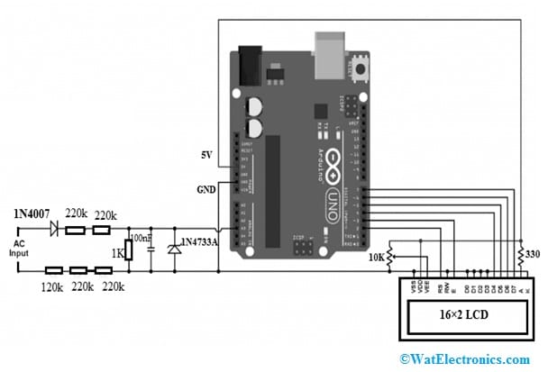
A simple AC voltmeter using an Arduino Uno board circuit is shown below. This circuit is used to measure AC voltage where the value of voltage can be printed above the 16×2 LCD display. This voltmeter measures 110V or 220V or 380V AC voltages with 50/60Hz frequency.
The required components to make this circuit mainly include; an Arduino UNO board, 16×2 LCD screen, 330-ohm resistor, 10k ohm potentiometer/variable resistor, resistors like 220k ohm-4, 120k, 1k ohm, ceramic capacitor-100nF, 5.1V 1N4733A Zener diode, 1N4007 diode, jumper wires, and breadboard. Connect the circuit as per the following circuit shown below.

AC Voltmeter with Arduino Board
The AC input is given to the AC voltmeter circuit as shown in the above diagram wherever the 1N4007 diode is utilized for removing the negative half cycles.
Once we obtain the positive AC voltage signal part, then it moves toward a voltage divider because the Arduino board cannot deal with above 5Volts. Here, the voltage divider is designed with 4-220k ohm resistors, 120k ohm resistor-1 & 1k ohm resistor-1, thus the voltmeter impedance is about 1 mega-ohm (M ohm). The Arduino uno board simply reads the voltage supply across the 1kilo ohm resistor which is equivalent to the input voltage.
Thus, if the input voltage is 220Volts then the voltage across the 1kilo ohm resistor is 220mV or 0.220V which is known as RMS value. The voltage signal noise can be stabilized & eliminated by a 100nF ceramic capacitor across the 1kilo ohm resistor. The 1N4733A Zener diode is utilized for protecting the Arduino from voltages superior to 5.1 volts. The 16×2 LCD screen is used to display the input voltage value wherever:
- The RS pin of the LCD is connected to digital pin-2 of Arduino.
- The E pin of the LCD is connected to digital pin-3 of Arduino.
- The D4 pin of the LCD is connected to the digital pin-4 of the Arduino.
- The D5 pin of the LCD is connected to the digital pin-5 of the Arduino.
- The D6 pin of the LCD is connected to the digital pin- 6 of Arduino.
- The D7 pin of the LCD is connected to the digital pin- 7 of the Arduino.
- The VSS, RW, D0 to D3 & K pins of LCD are connected to the GND of Arduino.
- The VEE pin of the LCD is connected to the 10k ohm variable resistor output.
- The VDD pin of the LCD is connected to the 5V of Arduino & A-pin of the LCD is connected to the 5V pin of Arduino through a 330-ohm resistor.
- The VEE pin of the LCD is used for controlling the variation of the LCD. In the LCD, the A & K pins are the anode and cathode backlight LED pins
Arduino Code
#include <LiquidCrystal.h> // include Arduino LCD library
// LCD module connections (RS, E, D4, D5, D6, D7)
LiquidCrystal lcd(2, 3, 4, 5, 6, 7);
void setup(void) {
lcd.begin(16, 2); // set up the LCD’s number of columns and rows
lcd.setCursor(0, 0);
lcd.print(“RMS Voltage:”);
analogReference(INTERNAL); // set ADC positive reference voltage to 1.1V (internal)
}
// get maximum reading value
uint16_t get_max() {
uint16_t max_v = 0;
for(uint8_t i = 0; i < 100; i++) {
uint16_t r = analogRead(A3); // read from analog channel 3 (A3)
if(max_v < r) max_v = r;
delayMicroseconds(200);
}
return max_v;
}
// main loop
void loop() {
char buf[10];
// get amplitude (maximum – or peak value)
uint32_t v = get_max();
// get actual voltage (ADC voltage reference = 1.1V)
v = v * 1100/1023;
// calculate the RMS value ( = peak/√2 )
v /= sqrt(2);
sprintf(buf, “%03u Volts”, v);
lcd.setCursor(0, 1);
lcd.print(buf);
delay(100);
}
// end of code.
The below Arduino code simply measures the input AC voltage’s RMS value by simply detecting the highest value of the half-wave & after that dividing it through √2.
Thus, Vrms = Vmax/√2
The Arduino board detects the highest value by simply reading the analog voltage on A3 (channel-3) multiple times. The get_max()function reads the voltage of the A3 channel hundred times throughout a period of above 20ms. The Arduino provides accurate measurement for an input of a sine wave AC voltage.
Please refer to this link for; Choosing resistor values for a diode.
1N4733A Zener Diode Applications
The applications of the 1N4733A zener diode include the following.
- Zener diodes have many specifications which are applied to different forms of electrical circuits.
- 1N4733A zener diode is used in voltage protection circuits.
- It can be used as a voltage regulator to change the voltage within several small circuits.
- These types of diodes can also be used as a waveform clipper once they are simply connected in series.
- It is used for Input voltage protection in Microcontrollers or ICs.
- It is used in voltage-stabilizing circuits.
- This diode is extensively used to avoid electronic circuits from high voltage.
- This diode is used as a voltage shifter to shift the o/p voltage.
- The 1N4733A is a Zener Diode used for stabilizing & also clipping electrical circuits through the maximum rating of power.
Please refer to this link for the 1N4003 Diode.
Please refer to this link for 1N4733A Zener Diode Datasheet.
Thus, this is an overview of the 1N4733A zener diode, pin configuration, features, specifications, working, and applications. A Zener diode is mainly designed to consistently allow the flow of current backward once a certain fixed Zener voltage is reached. These types of diodes are simply manufactured with a high range of Zener voltages & some diodes are still variable. Here is a question for you, who invented the Zener diode?