An SMD transistor is a surface-mount device transistor that can be directly soldered onto the surface of a PCB. The transistors which can be mounted in this way can detach more easily, so the circuit boards which use SMD transistors are very cheaper to produce as compared to others. These transistors are made up of semiconductor materials like Germanium/ Silicon. There are two kinds of SMD transistors like PNP type & NPN type and these transistors are marked with some codes to indicate the kind of semiconductor utilized. This article discusses one of the types of SMD NPN transistors like the MMBT2222a transistor, pin configuration, specifications, and its applications.
What is MMBT2222a Transistor?
The MMBT2222A is a popular surface-mount NPN transistor from Fairchild Semiconductor and it is the SMD (SOT-23) equivalent version of the 2N2222A Transistor. This transistor has 0.6A of collector current & 40V of collector-emitter voltage. This Transistor is generally used for medium power switching & amplification applications and also low power switching devices wherever space is a constraint.
MMBT2222A NPN transistor is reverse biased when the base pin of the transistor is held at GND, so both the collector & emitter terminals will be left open and this transistor is forward biased once a signal is given to the base pin of the transistor. MMBT222A transistor has the highest gain value of 300 and it decides the transistor’s amplification ability. The highest amount of current supplied throughout the Collector terminal is 600mA, thus we cannot connect any loads that use above 600mA of constant current & 800mA of peak current.
This transistor is biased by supplying current to the transistor’s base terminal where this current must be restricted to 5mAmps with 6V of base emitter voltage. The 40V of the highest voltage required across the load to get switched is 40V. Both the MMBT2222a transistor and equivalent MMBT2907A PNP transistor are combined together to make Class B amplifier & push-pull circuits.
Pin Configuration:
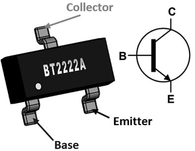
The pin configuration of the MMBT2222a transistor is shown below. This transistor includes three terminals which are discussed below.

MMBT2222a Transistor Pin Configuration
- Pin1 (Emitter (E)): The current flows out through this terminal.
- Pin2 (Base (B)): The transistor biasing can be controlled through this terminal.
- Pin3 (Collector (C)): This terminal allows the flow of current.
Features & Specifications:
The features and specifications of the MMBT2222a transistor include the following.
- It is a small signal Bi-Polar NPN Transistor.
- This transistor construction is based on the epitaxial planar die.
- Its contact plating is made with Tin material.
- The type of mounting is Surface Mount.
- It is ideal for low-power switching & amplification.
- Its Height x Width x Length is 1mm x 1.4mm x 3.05mm.
- Low Saturation Voltage (VCE) is below 300mV at 150mAmps.
- Its rise time is 25ns and the fall time is 60ns correspondingly.
- It is completely Lead-Free & RoHS Compliant
- Its minimum operating temperature is -55°C.
- Its maximum power dissipation is 300mWatts.
- Its frequency is 300MHz.
- Its maximum power is 350mW.
- Its collector-to-emitter breakdown voltage is 40V.
- Its maximum collector current is 1Amps.
- Its saturation voltage from the collector to the emitter terminal is 300mV.
- Its emitter to base voltage (VEBO) is 6Volts.
- Its maximum collector current is 600mAmps.
- Its collector-to-base voltage (VCBO) is 75Volts.
- Min hFE is 100.
- Package or Case is TO-236-3, SOT-23-3 & SC-59.
- Its operating temperature is 150°C TJ.
- Its Moisture Sensitivity Level or MSL is 1 (Unlimited).
- Its operating temperature maximum is 150°C.
- Its maximum frequency is 300MHz.
- Its complementary PNP-type transistor is MMBT2907A.
The equivalent MMBT2222a transistors are:
2N2222A, BC549, MMBT2907A, BC636, 2N2369, BC639, 2N3055, 2N2222, 2SC5200 and 2N3906.
Latch Circuit using MMBT2222a Transistor
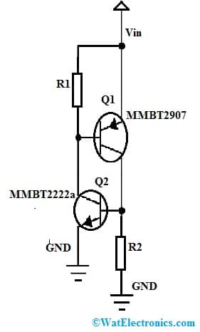
The circuit diagram of a simple and inexpensive latch circuit using an MMBT2222a transistor is shown below. This circuit is used to provide fault protection within power supplies using some electronic components. Generally, it is a silicon-controlled rectifier implemented through discrete components. The required components to make this latch circuit mainly include an MMBT2222a transistor, an MMBT2907 transistor, resistors 3.09K, and a voltage supply.

Latch Circuit using MMBT2222a Transistor
Working
The above schematic diagram uses a PNP/NPN emitter follower pair which is used to buffer the control IC output. So this increases the driveability of the controller potentially & moves the power dissipation of the drive to the exterior components.
First, the two transistors in the above latch circuit are normally off. To enable the latch circuit, you need to drive either the PNP transistor base terminal low or the NPN transistor’s base terminal high until any of the transistors activate. So this makes the collector terminal to allow the flow of current & turn ON the other transistor which further activates the original transistor.
This circuit latches in a regenerative manner. The flow of current is restricted only by the source impedance & the characteristics of the transistor allowing this latch circuit to discharge a capacitor quickly.
The main characteristic of this latch circuit is that you can establish the SCR holding current by selecting the values of the resistor. To remain on the latch once being fired, there has to be enough voltage across the two BE junctions of the transistors to remain them ON so that the circuit latches.
If the latch is coupled across a capacitor that is fed through a small current, then the latch will discharge the capacitor. When the current within the circuit drops under the holding current, then it will turn off.
Advantages Disadvantages
The advantages of the MMBT2222a transistor include the following.
- These transistors are available in small sizes.
- It is a small signal NPN transistor.
- The surface mount package of this transistor will make it to use in compact electronic designs wherever space is narrow.
- Its fast switching speed & good gain characteristics will make it to use in a wide range of electronic applications.
- One of the main benefits of this transistor is its high current gain.
The disadvantages of the MMBT2222a transistor include the following.
- As compared to other transistors, these transistors have limited current & voltage ratings so not suitable for high-power applications
- To get desired performance, they need extra components like resistors, capacitors, etc
Applications
The applications of the MMBT2222a transistor include the following.
- The MMBT2222A NPN transistor is mainly used in amplifier & switching electronic circuits because of its fast switching speed & high current gain like music players and blinking LEDs to digital logic gates.
- These transistors are used in switching circuits for controlling low current loads which include solenoids, pumps, LEDs, and many more.
- These are used in different driver modules like LED driver, Relay driver, etc.
- These are used in rectifiers, inverters, and Darlington pair design circuits.
- These NPN transistors are used for controlling motor speed.
- It is ideal for switching & power applications within several industries.
- These are used in applications that require small form factors.
- This transistor allows for amplifying low-level signals with minimum distortion because of its high current gain. So, it is used in signal processing circuits, audio amplifiers, and other applications wherever signal amplification with high fidelity is significant.
Interface of MMBT2222a transistor to microcontroller:
To interface the transistor to the microcontroller connect it as shown below
-
- Connect the Collector (C) pin to the positive supply voltage of the load you want to control.
- Connect the Emitter (E) pin to the ground (GND) of your power supply and the ground of the Arduino.
- Connect a resistor (the base resistor) between the Base (B) pin and the digital pin of the Arduino that you want to use for control.
Base Resistor Calculation:
- Calculate the value of the base resistor (Rb) using Ohm’s Law: Rb = (Vb – Vbe) / Ib, where Vb is the voltage supplied to the base, Vbe is the base-emitter voltage (usually around 0.7V), and Ib is the base current (typically a small fraction of the collector current).
Load Connection:
- Connect one end of your load (e.g., an LED with a current-limiting resistor, or a relay coil) to the Collector (C) pin of the transistor. Connect the other end of the load to the positive supply voltage.
Code to interface Transistor to microcontroller
const int controlPin = 3; // Replace with the actual digital pin number
void setup() {
pinMode(controlPin, OUTPUT);
}
void loop() {
digitalWrite(controlPin, HIGH); // Turn ON the transistor and the load
delay(1000); // Keep the load ON for 1 second
digitalWrite(controlPin, LOW); // Turn OFF the transistor and the load
delay(1000); // Keep the load OFF for 1 second
Please refer to this link for Precautions to be taken while connecting a Transistor to Microcontroller.
MMBT2222a in Home Appliances:
The MMBT2222A transistor can be used in various ways in home appliances, especially for switching and controlling various components within these appliances. Here are a few examples of how the MMBT2222A transistor could be used in different home appliances:
Lighting Control (LED Dimming):
- It can be used to control the brightness of LEDs in lighting fixtures. By connecting the transistor as a switch between the LED and a power supply, you can use an Arduino or other microcontroller to vary the current flowing through the LED, effectively dimming it.
Motor Control (Fan Speed):
- In appliances like fans, the MMBT2222A can be used to control the speed of a motor. By using the transistor to switch the motor on and off, you can achieve different fan speed levels.
Switching High-Power Components:
- It can act as a buffer between a microcontroller’s low-power output and high-power devices like motors, solenoids, or relays. This prevents the microcontroller from directly handling the high current these components require.
Timer and Delay Circuits:
- The transistor can be used to create timer and delay circuits. For example, it can control the activation of a component (e.g., a pump or a valve) after a specific time delay, which can be useful in appliances like washing machines or irrigation systems.
Temperature Control (Heating Elements):
- The transistor can control the power supplied to heating elements in appliances like ovens or toasters. By modulating the power, you can achieve precise temperature control.
Audio Amplification:
- While the MMBT2222A is not a high-power transistor, it can still be used for basic audio amplification in smaller appliances, such as portable radios or intercom systems.
Sensor Signal Amplification:
- The transistor can amplify weak sensor signals, making it useful in appliances with sensors, such as air purifiers that use sensors to detect air quality.
Remote Control Signal Amplification:
- The transistor can be used to amplify remote control signals, helping to improve the range of remote-controlled appliances.
Please refer to this for How to Select a Transistor.
It’s important to note that though the MMBT2222A is versatile, it has limitations in terms of voltage, current, and power handling. Therefore, it may not be suitable for very high-power applications. Please refer to this link for MMBT2222a Transistor Datasheet.
Thus, this is an overview of MMBT2222A NPN BJT which is commonly used within electronic design because of its excellent performance within fast-switching & amplifier circuits. This transistor operates in high-speed switching modes & provides better performance across extensive temperature ranges. As compared to 2N2222A, these transistor specifications are the same but their packages are different. The 2N2222A transistor is available in a TO-18 metal package whereas the MMBT2222A is available in a tiny SOT-23 plastic package. Here is a question for you, what is the MMBT3904 transistor?