The PIC microcontroller (peripheral interface controller) was first launched in 1993 by Microchip Technologies. After that, Microchip technologies have developed many PIC series microcontrollers which are used for lighting applications to the advanced ones. This microcontroller is based on Harvard architecture. PIC microcontrollers allow simple programming as well as interfacing within the design of embedded systems. At present, most of the PIC microcontrollers used are 8-bit type but Microchip introduced 16-bit & 32-bit based PIC microcontrollers. This article discusses one of the series of PIC microcontrollers like the PIC16f676 microcontroller, pinout, architecture, circuit, and its applications.
What is PIC16f676 Microcontroller?
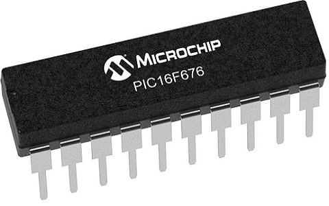
PIC16F676 is an 8-bit CMOS PIC microcontroller from the PIC16F series developed by Microchip Technology. This microcontroller has 14 pins with a high-performance RISC CPU so it is an ideal choice for many electronic applications like industrial automation or embedded systems. This microcontroller is based on flash wherever a high-performance-based CPU adds the processing speed. This microcontroller is available in three packages PDIP, TSSOP & SOIC. This chip has fewer pins & memory space as compared to other types of PIC controllers but, flash-based technology will make this chip well-matched with external devices.

PIC16f676 Microcontroller
Features & Specifications
The features and specifications of the PIC16f676 microcontroller include the following.
- The PIC16F676 microcontroller’s high-performance flash memory helps in improving the microcontroller’s processing speed.
- PIC16F676 includes program memory with 1.7kB of memory space whereas EEPROM & RAM memories are 128 bytes & 64 bytes correspondingly.
- A single 10-bit ADC module within the device comes through eight analog channels. So this ADC module plays a very important role in interfacing the sensor & changing the values from analog to digital.
- This microcontroller provides direct 12 GPIO I/O Pins within a small single package, used for driving low voltage devices directly.
- This microcontroller has an internal CLK that can be utilized by initializing ing through the program.
- This controller has an automatic sleep ability that saves more power.
- It has 8 ADC channels that store the 8-bits data.
- This controller includes two internal timers like Timer0 & Timer1. The input of Timer 1 can be simply controlled from an exterior pin.
- This has serial programming pins which are used for programming it through two pins.
- This controller has an analog comparator which has two inputs & outputs.
- The standby current of this PIC microcontroller at 2V is 1nA.
- The operating current at 2V is 100uAmps but the operating voltage changes by the oscillator.
- The internal oscillator of this microcontroller is 4MHz.
- This microcontroller’s operating voltage ranges from 2.0V to 5.5V.
- Its maximum CPU speed is 1MHz.
- Its flash memory is 1024 words, EEPROM – 128 bytes, and SRAM – 64 bytes.
- This has 8 analog to digital channels although they use only a 10-bit register for storing the converted data.
- Its operating temperature ranges from -40 – 125 degrees whereas its storage temperature ranges from -65 -150 degrees.
- The highest voltage of this microcontroller above all pins should not be above the power pin & current should not be above 250mA.
- The replacement of PIC16F676 is PIC16F630 and similar microcontrollers are; PIC16F636, PIC16F684, PIC16F84A, PIC16F877A & PIC18F46K22.
Pin Configuration
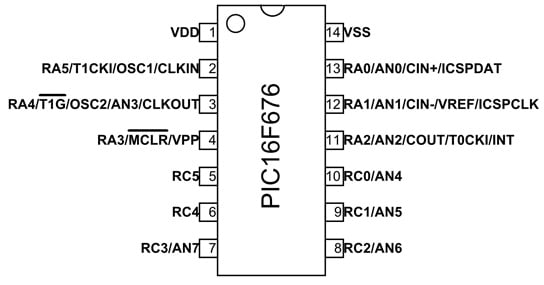
The pin configuration of the PIC16f676 microcontroller is discussed below.

PIC16f676 Microcontroller Pin Configuration
- Pin1 (VDD): It is a voltage supply pin.
- Pin2 (RA5/T1CKI/OSC1/CLKIN): RA5 is a Pin-5 of Port –A, T1CKI is a Timer-1 external CLK input, OSC1 is an Oscillator pin-1 and CLKI is an external CLK input source.
- Pin3 (RA4/T1G/OSC2/AN3/CLKOUT): RA4 is a Pin4 of Port-A, T1G is a Timer-1 gate, OSC2 is an Oscillator pin-2 and AN3 is an analog input-3 and LKO is a CLK source o/p.
- Pin4 (RA3/MCLR/VPP): RA3 is a Pin3 of Port-A, MCLR is the master CLR Input, and VPP is a programming voltage.
- Pin5 (RC5): RC5 is a Pin-5 of port C.
- Pin6 (RC4): It is a pin-4 of Port C.
- Pin7 (RC3/AN7): RC3 is pin-3 of Port C and AN7 is analog input-7.
- Pin8 (RC2/AN6): RC2 is a pin of Port-C2 and AN6 is an analog input-6.
- Pin9 (RC1/AN5): RC1is a pin of Port-C1 and AN5 is an analog input-5.
- Pin10 (RC0/AN4): RC0 is a pin of Port-C0 and AN4 is an analog input-4.
- Pin11 (RA2/AN2/COUT/T0CKI/INT): RA2 is a pin-2 of Port-A, AN2 is analog input-2, COUT is an output of the comparator, T0CKI is a Timer-0 CLK input and INT is an external interrupt.
- Pin12 (RA1/AN1/CIN-/VREF/ICSPCLK): RA1is a Pin-1 of Port-A, AN1is analog input-1, CIN is an input of comparator and VREF is an external voltage reference and ICSPCLK is serial programming CLK.
- Pin13 (RA0/AN0/CIN+/ICSPDAT): RA0 is a Pin-0 of Port-A, AN0 is an analog input-0, CIN+: is an input of the comparator and ICSPDAT is a serial programming data I/O.
- Pin14 (VSS): It is a GND pin.
PIC16f676 Microcontroller Architecture
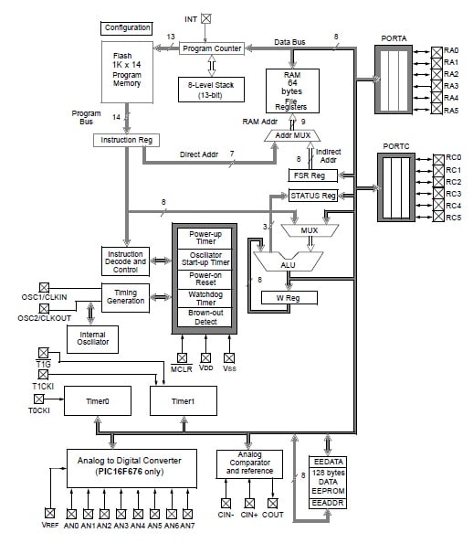
The functions of the PIC16f676 microcontroller are discussed below.

PIC16f676 Microcontroller Architecture
MCLR or Master Clear Reset
The master clear reset is an exterior reset of the controller that is executed by simply keeping this pin LOW. This MCLR pin doesn’t depend on the internal resets which include the noise filter for detecting & removing the small pulses within the path.
Timer
PIC16F676 microcontroller includes two timers like 8-bit & 16-bit timers. These timers are available with a CLK select capability and can be used in two ways like a timer & a counter. The timer mode is mainly used for creating a delay within any function whereas a counter mode is used for counting the internal functions.
ICSP (In-Circuit Serial Programming)
ICSP is also known as In-system programming or In-circuit serial programming which is added within the device to assist in device programming after installation within a circuit board. ICSP improves the flexibility of the microcontroller.
Watchdog Timer
The watchdog timer function is used to reset the microcontroller if the running program of the controller gets stuck within an infinite loop. This function is very hard for rebooting the whole system when a malfunction occurs. These timers can save time & get the system back to its first position devoid of human interference.
Compiler
Compiler software is used wherever we write a program to perform preferred functions on the PIC microcontroller. Microchip has its own typical compiler known as MPLAB C18 Compiler which can be obtained from the Microchip Site.
Memory Layout
The memory of this PIC microcontroller is separated into three types program memory ROM, data memory (RAM) & data EEPROM & FLASH. The program memory is used to store the program permanently and it comes through a 13-bit program counter to address the space of 8k x 14 program memory.
The data memory is also known as RAM memory which is used to store the program for the moment it mainly depends on the power supply source. The data memory eliminates the stored program whenever the power supply is turned off.
Data EEPROM & FLASH
During normal operation, both the data EEPROM & Flash program memory is readable & writable. This memory is not mapped directly within the space of the register file. In its place, it is addressed indirectly throughout the SFRs or Special Function Registers like EECON1, EECON2, EEDATA, EEDATH, EEADR & EEADRH which are used for reading & writing this memory: The data EEPROM allows single-byte read & writes whereas the flash program memory simply allows single-word reads & four-word block writes.
Special Function Registers (SFRs)
The SFRs are mainly utilized by the CPU as well as peripheral functions to control the device’s preferred operation. These registers are classified into two sets; core & peripheral.
STATUS Register
The Status register has the arithmetic condition of the ALU, the Reset condition of the PIC & the Bank Selection bits. This status register is used mostly for switching between banks. This register can be the target for any instruction similar to any other type of register.
W Register
The W register or work register is the most commonly used 8-bit register in this microcontroller. This type of register is similar to the accumulator within other microprocessors. This is a general register so you can place any value that you desire. When you have allocated a value to this register then you can include it to one more value, otherwise shift it.
Instruction Sets
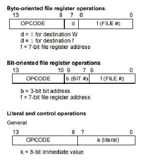
The instruction set of the PIC16F676 microcontroller is extremely orthogonal & is comprised of three main categories like byte-oriented, bit-oriented, and literal & control operations. Every instruction in this microcontroller is a 14-bit word which is separated into an opcode, which indicates the type of instruction & single or many operands, Further, these can specify the instruction operation The formats for every category can be presented in the following figure.

PIC16f676 Microcontroller Instruction Sets
Byte Oriented Instructions
For these types of instructions, the ‘f’ denotes a designator of the file register & ‘d’ denotes a destination designator. Here, the file register designator indicates which file register is to be utilized by the instruction. The destination designator indicates where the outcome of the process is to be located. If the destination designator like d is ‘0’, then the outcome will be placed within the ‘W’ register. If the destination designator is ‘1’, then the outcome is located within the specified file register in the instruction.
Bit Oriented Instructions
For these types of instructions, ‘b’ indicates a bit field designator and it chooses the affected bit through the operation whereas ‘f’ indicates the file address where the bit is placed.
For Literal and Control Operations
For the operations of literal & control operations, ‘k’ signifies an 8-bit/11-bit constant, otherwise literal value. A single instruction cycle includes four oscillator periods. For 4 MHz of an oscillator frequency, this provides one micro sec of normal instruction execution time. All the instructions are simply executed in a single instruction cycle, except if a conditional test is right, or the PC (program counter) is modified as an outcome of an instruction. Once this happens, the execution uses two instruction cycles, with the next cycle performed as a NOP. The examples of all instructions utilize the ‘0xhh’ format to signify a hexadecimal number, wherever ‘h’ indicates a hexadecimal digit.
Digital Voltmeter Circuit with PIC16F676 Microcontroller
The digital voltmeter circuit to display three digits using the PIC16F676 microcontroller is shown below. The required components to make this circuit mainly include; PIC16F676 Microcontroller, seven-segment display, BC 547 transistors, resistors-1K, 33K, 50K, 47K, and capacitors-0. 1u, 0-30V supply. Connect the circuit as per the circuit diagram shown below.

Digital Voltmeter Circuit with PIC16F676 Microcontroller
Working
The PIC16F676 microcontroller used in this circuit is to read analog signal (voltage) and displays the three digits value on the 7-segment display. Generally, PIC microcontrollers have 8-bit or 10-bit on-chip ADC modules. But in this circuit, the PIC16F676 microcontroller uses only a single channel for measuring input voltage for another pin set like digital I/O.
The input voltage from the above circuit is divided through R1 & R2 voltage dividers. The suitable display of full-scale voltage can be adjusted through variable resistor VR1 connected with R2 in parallel. The analog input comes from the input voltage divided from AN3.
The RA0 to RA2 digital output will turn ON or OFF the digits within the display. The display is driven through the RC0 to RC5 & RA5 pins which will be decoded through software with CCS C compiler for programming. The seven-segment code is a changed input voltage form on RA3. For each 5 ms, the interrupt is set on the timer when all digits scan around 66 Hz frequencies. So for each 5 ms, one digit will be turned ON only.
Code
#include <16F676.h>
#device adc=10
#fuses INTRC_IO,NOWDT,PUT,NOPROTECT,BROWNOUT,NOMCLR
#use delay (clock=4000000) // 4MHz clock
#rom 0x3ff={0x3444}
#byte PORTA = 0x05
#byte PORTC = 0x07
#byte TRISA = 0x85
#byte TRISC = 0x87
#define SPORTA PORTA
#define SPORTC PORTC
#define TICKS_BETWEEN_INTERRUPTS 5000 //5000
#define INTERRUPT_OVERHEAD 35
#define TMR1RESET (0xFFFF-(TICKS_BETWEEN_INTERRUPTS-INTERRUPT_OVERHEAD))
const char SegCode[11] = {0x40,0x57,0x22,0x06,0x15,0x0C,0x08,0x56,0x00,0x04,0xFF};
// 0 1 2 3 4 5 6 7 8 9
const char Column[3] = {0x02,0x01,0x04};
static char Segment[3] = {0x7f,0x7f,0x7f};
static unsigned char ColCount=0x00;
void CPU_SETUP(void);
void Display(void);
void HTO7S(unsigned int32 Num);
byte i;
unsigned int32 result;
#INT_TIMER1
void Timer1(void)
{
set_timer1(TMR1RESET);
Display();
}
void main()
{
unsigned char i;
CPU_SETUP();
while(true)
{
result=0;
for (i=0;i<20;i++)
{
set_adc_channel(3);
delay_ms(1);
result=result+read_adc();
}
//result = 0x3fe;
HTO7S(result/20);
delay_ms(200);
}
}
void CPU_SETUP()
{
setup_comparator(NC_NC_NC_NC); // not use comparator module
setup_adc_ports( sAN3 | VSS_VDD);
setup_adc(ADC_CLOCK_DIV_64);
TRISA=0b00011000;
PORTA=0x27;
TRISC=0b00000000;
PORTC=0x37;
setup_timer_1(T1_INTERNAL|T1_DIV_BY_1);
set_timer1(TMR1RESET);
enable_interrupts(GLOBAL);
enable_interrupts(INT_TIMER1);
}
//————————————-
// Display routine
//————————————-
void Display()
{
PORTA = 0b00100111; // off all digits column and Segment G
PORTC = 0b00111111; // off segment a-f
delay_cycles(2);
if (ColCount>=3)
ColCount=0;
SPORTC = Segment[ColCount];
SPORTA = ((Segment[ColCount] & 0b01000000)>>1) | (Column[ColCount]^0x07);
ColCount++;
}
//————————————–
// Convet HEX 2 byte to 7-Segment code
//————————————–
void HTO7S(unsigned int32 Num)
{
unsigned int32 res;
Segment[0]=SegCode[30*Num/10230];
if (Segment[0]==0x40)
Segment[0]=0xFF;
res = 30*Num%10230;
Segment[1]=SegCode[10*res/10230];
res=10*res%10230;
Segment[2]=SegCode[10*res/10230];
}
Applications
The applications of the PIC16f676 microcontroller are discussed below.
- PIC16f676 microcontroller is an excellent choice to use in electronic applications like industrial automation & embedded systems.
- These are used in different medical devices like pacemakers, heart monitors, insulin pumps, etc.
- These PIC microcontrollers are used in GPS, security systems, custom circuits prototyping, central heating projects, and student-level projects for motor controlling & sensor interfacing.
- This chip is used for industrial, automotive & entry-level consumer product applications that need field re-programmability.
- These are extremely helpful to perform automation in several electronic devices and it also provides easy to configure & accessible interface.
- This microcontroller is used in beginner applications mostly development programs, student projects, and many more.
- These are used in mini projects like scrolling displays, meters, etc.
- This microcontroller is used in devices that need ADC with respect to time.
Please refer to this link for PIC16f676 microcontroller Datasheet.
Thus, this is an overview of the PIC16f676 microcontroller, pin configuration, specifications, architecture, circuit, working, and its applications. This is an 8-bit CMOS microcontroller with a 14-pin interface with a very high-performance RISC CPU. This small IC includes everything you require to build up individual student-based projects. As compared to other types of PIC microcontrollers, this microcontroller has less space for memory & pins but, flash-based technology will make this controller compatible with external devices. By using this microcontroller, various functions can be done without purchasing any external components, which makes your project extremely cost-effective & lightweight that uses very less space. Here is a question for you, what is a pic24 microcontroller?