Transistors are semiconductor devices mainly used for switching or amplifying electrical signals & power. In modern electronics, these components are basic building blocks that include a minimum of three terminals for connecting in an electronic circuit. Transistors are generally classified into three types like BJTs, FETs & IGBTs. These transformers are also available in different types based on different functions like small switching, small-signal, power, phototransistor, UJT & high frequency. Similarly, transistors that are connected in multi-configuration are known as Darlington configurations. These transistors are available in different series like NZT, KST, KSP, PZT & MMBT. This article discusses an overview of the MMBT3904 transistor, pin configuration, specifications, and applications.
What is MMBT3904 Transistor?
MMBT3904 is an NPN SMD transistor that is available within the SOT-23 package. This transistor has 40V of VCE & 200mA of collector current. This transistor can be used as a small signal-switching transistor. This transistor is made with plastic or epoxy material to oppose high-temperature values. These are used to drive modules like relay drive, LED drive and also used in amplifier modules like audio amplifiers, signal amplifiers, etc.
MMBT3904 NPN transistor’s emitter & collector terminals will be reverse biased whenever the base pin is connected to GND & when a signal is given to the base pin, it will be forward biased. This transistor has a maximum gain value of 300, so this value will decide the transistor’s amplification capacity. The highest amount of current supplies throughout the collector terminal is 200mA, so using this transistor, connecting loads that consume above 200mA is not possible.
For biasing a transistor, the current needs to be supplied to the base pin and this current must be limited to 5mAmps. Whenever this MMBT3904 transistor is completely biased, it allows 200mA of current to supply across the emitter & collector which is known as the saturation region. The typical voltage allowed across the VCE or VCB could be 40V and 60V equally. Whenever the base current is detached then this transistor will be completely off, so this stage is known as the Cut-off Region.
Pin Configuration:
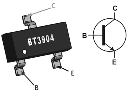
The pin configuration of the MMBT3904 transistor is shown below. This transistor includes three pins; an emitter, base, and collector which are discussed below.

MMBT3904 Transistor Pin Configuration
Pin1 (Emitter): It is the input terminal of the transistor where the current supplies from this terminal.
Pin2 (Base): This terminal is the trigger for this transistor.
Pin3 (Collector): This terminal allows the flow of current.
Features & Specifications:
The features and specifications of the MMBT3904 transistor include the following.
- It includes three pins.
- The type of package or case is TO-236-3, SOT-23-3 & SC-59.
- The element material of the transistor is Silicon.
- Its packaging is Tape & Reel.
- The type of polarity or channel is NPN.
- The type of mounting is surface mount
- Its maximum turn ON time is 70ns
- The MMBT3904 transistor collector to base voltage (VCB) is 60V.
- Its collector-to-emitter voltage (VCE) is 40V.
- Its emitter to base voltage (VEB) is 6V.
- The saturation voltage from collector to emitter ranges from 0.20 V to 0.30V.
- The MMBT3904 transistor’s collector current value is 200mA which is very helpful for driver applications.
- The power dissipation value of this transistor is 310 watts.
- The current gain value of this transistor ranges between 30 – 300 dB.
- The SMD transistor’s small-signal current gain value is 100 to 400hFE.
- The value of the bandwidth transition frequency is 300MHz.
- The junction temperature range of this transistor ranges from -55 to 150℃.
- The highest noise value of his transistor is 5dB.
- The thermal resistance of this transistor is 403℃/W
- Its rise time is 35nsc.
Equivalent & Complementary Transistors
The equivalent MMBT3904 transistors are; MMBT3904LT1G, FMMT2222A, MMBT4401, MMBTA06 & MMBTA05. The complementary MMBT3904 PNP transistor is the MMBT3904 NPN transistor. The combination of these two transistors can also be used in different applications.
Joule Thief Circuit with MMBT3904 Transistor
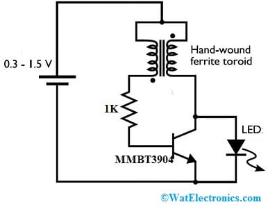
A joule thief circuit is a low-cost, small, and very simple self-oscillating voltage booster, used to drive an LED through an approximately dead battery. This circuit is also known as a joule ringer, blocking oscillator & vampire torch. The required components to make this circuit are; a ferrite toroid core, one resistor, a transistor, a battery & led. Connect the circuit as per the circuit shown below.

Joule Thief Circuit with MMBT3904 Transistor
Working
In this circuit, the magnetic field can be formed around the ferrite toroid due to the current supply throughout the wires. The additional current will make the transistor turn off & power toward the ferrite toroid will stop. Thus, the magnetic field can be changed into electrical energy which is given as o/p. When the magnetic field doesn’t exist, then again the transistor will turn on & conducts electricity to form again the magnetic field. This procedure quickly occurs to provide constant output power. The generated voltage spikes frequency throughout this circuit is above 5KHz.
In the above Joule Thief circuit, the inductance can be determined through the loops in the region of the ferrite toroid. So the inductance is more when the numbers of loops are more. Generally, when the inductance is increased then the flow of current throughout the circuit will be decreased & duty cycle will be increased. So, an increase in inductance will increase the circuit efficiency.
The application of this circuit is not only driving an LED through a dead battery and this circuit also assists in using nearly all the stored energy within a battery. This circuit can also be applicable in solar cell chargers, wall clocks, and battery chargers, wherever a low input voltage has to be improved for its application. This voltage booster circuit changes a low input constant voltage into a periodic higher output voltage. So this circuit is most frequently seen in lighting an LED through a dead AA battery.
How to Connect MMBT3904 Transistor to a microcontroller ?
To connect an MMBT3904 NPN transistor to a microcontroller, one should typically use the transistor as a switch to control higher current or voltage loads with the lower current and voltage signals from the microcontroller. Below is a basic guide on how to connect the MMBT3904 transistor to a microcontroller:
Components Needed:
- MMBT3904 NPN transistor
- Microcontroller (e.g., Arduino, Raspberry Pi, etc.)
- Load (e.g., LED, motor, relay, etc.)
- Current-limiting resistor (if connecting an LED)
Circuit Connections:
- Identify the pins of the MMBT3904 transistor. The transistor has three pins: the Emitter (E), the Base (B), and the Collector (C).
- Connect the Emitter (E) pin of the transistor to the ground (GND) of the microcontroller or the common ground of the circuit.
- Connect the Collector (C) pin of the transistor to the positive voltage supply (Vcc) or the positive terminal of your load.
- Place the load (e.g., an LED, motor, or relay) between the Collector (C) pin and the positive voltage supply (Vcc).
- Connect the Base (B) pin of the transistor to one of the digital output pins of the microcontroller.
Adding a Current-Limiting Resistor (for LED):
If you are connecting an LED as the load, you need to include a current-limiting resistor in series with the LED. The value of the resistor can be calculated using Ohm’s Law: R = (Vcc – V_LED) / I_LED, where V_LED is the forward voltage drop of the LED and I_LED is the desired LED current.
Controlling the Transistor:
Now, to control the load (LED, motor, relay, etc.), you can use the microcontroller to drive the Base (B) pin of the transistor. When you set the digital output pin connected to the Base (B) to a high logic level (usually 5V for most microcontrollers), current will flow from the microcontroller through the Base-Emitter junction, turning the transistor ON. This, in turn, allows current to flow from the Collector to the Emitter, energizing the load.
When you set the digital output pin to a low logic level (0V), no current flows through the Base-Emitter junction, and the transistor remains OFF, cutting off the current to the load.
Keep in mind that the MMBT3904 transistor has a maximum current and voltage rating, so make sure the load you are connecting does not exceed these specifications. Always check the datasheet of the MMBT3904 transistor for its specific characteristics and limitations.
Note: The specific connections and values may vary based on the requirements of your application and the microcontroller you are using. Always refer to the datasheets of the components for accurate information.
Please refer to this link for Precautions to be taken while connecting a Transistor to Microcontroller.
Advantages & Disadvantages
The advantages of the MMBT3904 Transistor include the following.
- It is suitable for portable equipment.
- It is a small load switch transistor with low saturation voltage & high gain.
- It is used for controlling voltage loads up to 40 volts.
- It is an ideal transistor for standard amplification & power switching.
- This transistor allows a maximum of 200mA of current to supply throughout the emitter & collector terminals when it is biased.
The disadvantages of this transistor are; it is a small signal transistor, sensitive to ESD, less used within high power applications, and the limited response of frequency at maximum currents.
Applications
The applications of the MMBT3904 Transistor include the following.
- MMBT3904 Transistors are used in LED drivers, motor drivers, relay drivers, etc.
- These transistors are used in audio amplifier and signal amplifier modules.
- These are used in home appliances & TV applications.
- These can be used for controlling voltage loads equal to 40 volts.
- It is an ideal transistor used for standard power amplification & switching applications.
- These transistors are used in portable equipment.
- These transistors are used in professional communication & telephony equipment.
Please refer to this for How to Select a Transistor.
Please refer to this link for MMBT3904 Transistor Datasheet.
Thus, this is an overview of MMBT3904 transistor-pin configuration, specifications, circuit, working, and applications. This transistor has an innovative design & packaging which will help in improving its consistency for the highest thermal performance. This transistor is packaged within the SOT-203 plastic set. Here is a question for you, what is the mmbt2222a transistor?