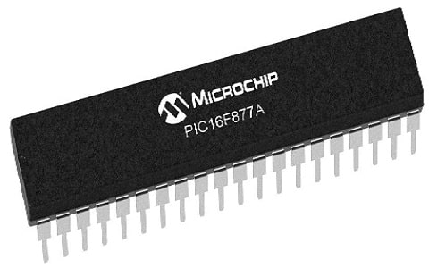
The peripheral interface controller microcontroller is one of the mostly used microcontrollers and which was launched by microchip technologies. This microcontroller includes different types of higher memory modules, microprocessor units, I/O ports, communication ports, timers/counters, interfacing ports, etc. This microcontroller is programmed using flash memory technology and it allows the stored data to be erased electrically & reprogrammed. So that it is very convenient to use in different kinds of devices like home automation, security, and safety devices & remote sensors. As compared to other microcontrollers, these microcontrollers are very advanced, so broadly used in different current electronics applications. So this article discusses an overview of one of the series of PIC microcontrollers like PIC16f877A microcontroller – pin configuration and its applications.
What is PIC16f877A Microcontroller?
The PIC16f877a microcontroller is one of the most famous microcontrollers used in different industries because this is extremely convenient to utilize and simple programming or coding. This microcontroller uses FLASH memory, so you can write and erase programs many times. This PIC microcontroller is used in various microcontroller-based projects and also in digital electronics circuits. Its cost is very low, its handling is easy, and very flexible to use in different applications.

PIC16f877A Microcontroller
Pin Configuration:
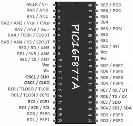
The pin configuration of the PIC16f877A microcontroller is shown below. This microcontroller includes 40 pins and these pins are separated into four ports PORTA, PORTB, PORTC, PORTD, and PORTE.

PIC16f877A Microcontroller Pin Configuration
PORTA (Pin2 to Pin7):
Port A includes 6 Pins from Pin2 to Pin7 like RA0 to RA5. Here RA0 pin is the first Pin label of Port A.
- Pin2 (RA0/AN0): This is the first pin of the port-A. So this pin is used as an analog pin and it is built in ADC.
- Pin3 (RA1/AN1): This is the analog i/p1.
- Pin4 (RA2/AN2/Vref-): This pin acts as the analog i/p2 or it acts as an analog -ve reference voltage.
- Pin5 (RA3/AN3/Vref+): This pin acts as the analog i/p3 or it acts as the analog +ve reference voltage.
- Pin6 (RA0/T0CKI): This pin acts as the CLK input pin to timer0, so the output type is open drain.
- Pin7 (RA5/SS/AN4): This pin is the analog i/p4. This pin acts as the slave selects for the synchronous serial port within this controller.
PORTB (Pin33 to Pin40):
Port B has a total of 8 Pins from Pin 33 to Pin 40 like RB0 – RB7. From all these PORTB pins, RB0 is utilized as the external interrupt pin whereas RB6 & RB7 pins are utilized as in-circuit debugger pins.
PORTC (Pin15 to Pin18 & Pin23 to Pin26):
Port C includes a total of 8 Pins that are not connected together. The first 4 Pins in this port are placed at Pin15 to Pin18 whereas the remaining pins are placed at Pin23 to Pin26.
- Pin15 (RC0/T1OCO/T1CKI): This is the first pin in PORTC which can be used as the CLK i/p of the first timer or o/p of the oscillator for the second timer.
- Pin16 (RC1/T1OSI/CCP2): This pin can be used as the input of the oscillator for timer 1/ input of the capture 2/compare 2 o/p/ output of PWM2.
- Pin17 (RC2/CCP1): This pin can be used as the input of capture1/ output of the compare1/ output of the PWM1.
- Pin18 (RC3/SCK/SCL): This pin is used as the SPI output (or) I2C modes & it can be the I/O for synchronous serial CLK.
- Pin23 (RC4/SDI/SDA): This pin is the data in pin of SPI or it can be used as the data I/O pin in I2C mode.
- Pin24 (RC5/SDO): This pin is the data out for SPI within the SPI mode.
- Pin25 (RC6/TX/CK): This pin can be used as the synchronous CLK or asynchronous transmit pin of USART.
- Pin26 (RC7/RX/DT): This pin can be used as the synchronous data pin (or) the receive pin of USART.
PORTD (Pin19 to Pin22 & Pin27 to Pin30):
Port D includes 8 Pins which are also not connected together. In this port, the first four pins are placed at Pin19 to Pin22 whereas the remaining pins are placed at Pin27 – Pin30. This port is a bidirectional I/O port. This port acts as the parallel slave port when the microprocessor bus needs to be interfaced.
PORTE (Pin8 to Pin10):
Port E includes 3 Pins from Pin8 to Pin10 like RE0 – RE2 where the ‘RE0’ pin is the first pin label for Port E.
- Pin8 (RE0/RD/AN5): This is the analog i/p 5 or it acts as a read control pin for the parallel slave port which is active low.
- Pin9 (RE1/WR/AN6): This is the analog i/p6 or it acts as the ‘write control’ for the parallel slave port which is active low.
- Pin10 (RE2/CS/A7): This is the analog input7, or it acts as the control select for parallel slave port which is also active low similar to read & write control pins.
Other Pins:
- Pin1 (MCLR): This is the master clear pin, so this pin resets the PIC microcontroller. Once this MCLR pin is active low, then it must be constantly given 5V & if 0V is given then the microcontroller will reset.
- Pin 11 & 32 (VDD): These are the positive supply pins for both the I/O & logic pins. So these two pins must be connected to 5Volts.
- Pin 12 & 31 (VSS): These two pins are the GND reference for both the I/O & logic pins. So these pins must be connected to zero potential.
- Pin13 (OSC1/CLKIN): This is the input pin of the oscillator or the external CLK i/p pin.
- Pin14 (OSC2/CLKOUT): This is the o/p pin of the oscillator. A crystal resonator is simply connected between two pins like pins 13 & 14 for providing external CLK to the microcontroller.
Features & Specifications:
The features and specifications of the PIC16f877A microcontroller are discussed below.
- It is a 40-pin microcontroller and uses RISC architecture.
- It includes five Ports Port A, Port B, Port C, Port D & Port E.
- This microcontroller includes 3-Timers where 2- timers are 8-bit Timers and one is 16 Bit.
- This microcontroller supports various communication protocols such as serial, I2C, and parallel.
- This PIC microcontroller supports both timer & hardware pin interrupts.
- It includes 35 smaller instruction sets.
- Its operating frequency is up to 20MHz.
- The operating voltage ranges from 4.2V to 5.5 volts.
- It does not include an internal oscillator.
- The highest current every PORT can source or sink is approximately 100mA.
- Its instruction execution is 200 ns.
- EEPROM data memory is 256 bytes.
- It includes two comparator
- It has a 10-bit ADC with 8 channels.
- It includes capture or compares or PWM functions.
- An asynchronous serial port is configured as either a two-wire I2C bus or a three-wire SPI.
- It includes a USART & a Parallel Slave Port.
- Its temperature range is -40° to +85°C.
- It has interrupt sources – 15.
- It has single-word instructions – 35.
- Its flash memory is 14.3 Kbytes.
- Its data SRAM is 368 bytes
- Its data EEPROM is 256 bytes
- Watchdog Timer through on-chip RC oscillator
- Protection for programmable code
- It has a sleep mode for power saving.
- Oscillator options in this are selectable.
- It has an 8-bit CPU.
- The type of program memory is flash
- Program memory is 14KB
- The speed of the CPU is 5 MIPS
- RAM is 368 Bytes.
- Data EEPROM is 256 bytes
Features
The in-built features provided by this microcontroller are discussed below.
ADC Module
This microcontroller includes an 8-bit ADC module with 8 channels. So, we can utilize 8 analog sensors through this PIC microcontroller.
Timers
This microcontroller has 3 timers 0, 1 & 2 which can be utilized in two modes either in timer (or) in counter mode. The main function of these timers is to generate PWM, delays, timer interrupts & external events counting. The 8-bit timer like Timer0 functions with internal/external CLK frequency. Once Timer0 is used in timer mode, then it operates with internal frequency whereas it is used in counter mode, then we activate it through an external CLK source. Likewise, Timer1 is a 16-bit timer, that operates in two modes and Timer2 is also an 8-bit timer that is used as a time base through PWM for the CCP module.
EEPROM
EEPROM is an inbuilt memory, which stores data permanently even if the PIC microcontroller is not enabled and data will stay there. Generally, it is used in electronics lock-based security projects.
PWM Modules
This PIC microcontroller includes two CCP modules which are also known as capture compare PWM modules. By using this microcontroller, we can generate 2-PWM signals easily. It supports 10 bits of maximum resolution.
Serial/UART Communication Pins
This microcontroller supports a single UART channel. In this microcontroller, UART pins are mainly used to provide serial communication for digital devices.
I2C Communication
PIC16F877A microcontroller supports this type of communication. This controller has a single module for this communication. Pin18 like RC3 & pin23 like RC4 are SCL & SDA pins correspondingly. Here, the serial clock line is SCL & serial data line is SDA.
Interrupts
PIC16F877A provides a total of eight types of interrupts like timer, external, PORT state change, UART, I2C, PWM, etc.
Comparator Module
This microcontroller includes a comparator module that includes two comparators that are used for analog signal comparison like comparators within electronic circuits. For these two comparators, the input pins are; RA0 to RA3 whereas the output is simply measured throughout RA4 & RA5.
Watchdog Timer
The watchdog timer is an on-chip separate oscillator from OSC1/CLKI that works freely. The watchdog timer also works even if the device is in sleep mode. This timer is mainly utilized to wake up the device from this mode & also to make this timer reset.
Sleep Mode
PIC16F877A microcontroller provides sleep mode operation where the device in this mode works at extremely low power. So waking up from this mode from interrupts resources such as UART interrupt, and timer1 interrupt, EEPROM can write a completion operation.
Brown out Detection
Brown-out detection detects a significant drop in power supply voltage. If the voltage supply falls from a certain limit, then it will produce an interrupt signal. So this configuration bit is utilized to enable or disable this circuitry.
Brown out Reset
The brown-out reset option is used to reset the device on brown-out interrupt signal detection from the BODEN signal. Once the voltage supply goes under the threshold for above 100 microseconds then Brown out reset and programmable code protection will arise & device will stay reset until the voltage increase to its nominal value.
Interfacing Servo Motor with PIC16f877A Microcontroller
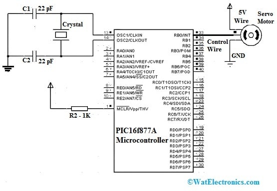
The interfacing of the servo motor with the PIC16F877A microcontroller is shown below. A servo motor is one kind of motor that works on the specified instructions. This motor rotates continuously until a power supply is applied to them & it stops rotating only once the power supply is turned off. This motor only turns to a certain level after that it stops rotating & remains for further instruction to perform the next action. This motor is controlled through servomechanism. This motor’s angular rotation as well as final movement can be dictated through position feedback.
The required components for this interfacing mainly include a servo motor, PIC16F877A microcontroller, two capacitors – 22pF & 1K resistor. Connect this circuit as per the circuit shown below. This interfacing is very simple to design. Generally, a servo motor includes three wires 5V, control, and GND. So, the 5V wire is connected to the power supply, the control wire is connected directly to the PIC microcontroller’s RB0 pin, and the GND pin is connected to GND.

Interfacing Servo Motor with PIC16f877A Microcontroller
This control pin of the motor is helpful in providing the necessary angular displacement of the servo motor. The servo motor angular rotation is restricted to 0° to 180°. So we can control the rotary motion of the motor with the highest precision with a pulse whose width is changed to achieve the preferred angle. Here, a pulse is given to the servo motor after each 20ms. The motor’s angular position can be decided through the pulse length.
Code
// Servo Motor PWM Interface with PIC16F877A Microcontroller
// Compiler: mikroC PRO for PIC
// Include necessary header files
#include <built_in.h>
// Define constants
#define PWM_PERIOD 20000 // PWM period in microseconds
#define SERVO_MIN 1000 // Minimum duty cycle for servo control
#define SERVO_MAX 2000 // Maximum duty cycle for servo control
// Initialize PWM module
void PWM_Init()
{
TRISC.F2 = 0; // Set CCP1 pin as output
CCP1CON = 0x0C; // Configure CCP1 module for PWM mode
CCPR1L = 0x00; // Initialize PWM duty cycle low byte
CCP1CON |= 0x0F; // Enable PWM output
T2CON = 0x04; // Set prescaler to 1:16 for Timer2
}
// Control servo motor angle
void Servo_SetAngle(int angle)
{
unsigned int duty_cycle;
// Calculate duty cycle based on desired angle
duty_cycle = map(angle, 0, 180, SERVO_MIN, SERVO_MAX)
// Set PWM duty cycle
CCPR1L = duty_cycle >> 2; // Set PWM duty cycle high byte
CCP1CONbits.CCP1X = duty_cycle & 0x02; // Set PWM duty cycle low byte
CCP1CONbits.CCP1Y = duty_cycle & 0x01;
}
// Map function to scale a value from one range to another
long map(long x, long in_min, long in_max, long out_min, long out_max)
{ return (x – in_min) * (out_max – out_min) / (in_max – in_min) + out_min;
}
// Main program
void main()
{
int angle = 0; // Initial angle of the servo motor
PWM_Init(); // Initialize PWM module
while (1)
{
// Rotate servo from 0 to 180 degrees
for (angle = 0; angle <= 180; angle++)
{
Servo_SetAngle(angle);
Delay_ms(10); // Delay between angle changes
}
// Rotate servo from 180 to 0 degrees
for (angle = 180; angle >= 0; angle–)
{
Servo_SetAngle(angle);
Delay_ms(10); // Delay between angle changes
}
}
}
In the above code we use the CCP1 module of the PIC16F877A microcontroller to generate the PWM signal for controlling the servo motor. The TRISC.F2 = 0; statement configures the CCP1 pin as output pin. The CCP1CON register is configured to enable PWM mode and the duty cycle is set using CCPR1L and CCP1CONbits.CCP1X and CCP1CONbits.CCP1Y bit.
When you use the above code ensure that you have configured the mikron project setting to match the PIC16F877A microcontroller and the oscillator frequency you are using.
Based on the specification of the servo motor you use adjust the PWM_PERIOD, SERVO_MIN and SERVO_MAX values .
Applications
The applications of the PIC16f877A microcontroller are shown below.
- PIC16F877A microcontroller is used in many projects.
- This microcontroller is used in digital electronics circuits.
- This PIC microcontroller is used in a number of devices like remote sensors, safety devices, industrial instruments & home automation.
- This microcontroller is applicable in areas wherever microcontrollers have never been utilized before as in timer functions & microprocessor applications.
- PIC16F877a is normally utilized in embedded system projects such as bank security systems, home automation systems, and many more.
- These types of microcontrollers are used broadly in modern electronics applications.
- It is used in various DIY projects.
- This microcontroller is used in different projects where various I/O interfaces & communications are required.
- It is used to replace the Arduino board.
- It is used in A/D applications in industrial, automotive, consumer applications, different appliances, etc.
Please refer to this link for the PIC16f877A microcontroller Datasheet.
Thus, this is an overview of PIC16f877A microcontroller – pin configuration, features, specifications, circuit, and working with applications. Here is a question for you, who invented the PIC microcontroller?