There are different communication technologies existing for communication between IoT devices but Bluetooth & Wi-Fi Technology is very famous ones. These two communication technologies have some limitations like access points, limited range, high power consumption, etc. Similarly, local area networks & mobile networks also have high power consumption and are quite expensive too. IoT industries from the past few years have launched many technologies but they are not perfect. So to overcome these issues, LoRa technology was introduced in the IoT field for transmitting data to very long distances without much power utilization. So, this technology is very helpful in performing ultra-long-range transmission with less power consumption. There are various LoRa RF module receivers available like SX1276, SX1277, SX1278, and SX1279. This article discusses an overview of an SX1278 Lora RF Module – working with applications.
What is SX1278 Lora RF Module?
The SX1278 is a Lora RF transceiver module that is used to provide spread spectrum communication for very long ranges and also high interference immunity whilst reducing current utilization. This is a low-cost RF transceiver module from Semtech Corporation. These modules are suitable for low data rate & low range applications due to high sensitivity and high power output. This LoRa RF module works at 1.8 to 3.6V with an additional low standby current so that it can be used in battery-powered applications. LoRa technology provides major benefits in both selectivities as well as blocking above conventional modulation methods, resolving the usual design compromise between power consumption, interference immunity, and range.
Pin Configuration:
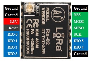
The pin configuration of the SX1278 Lora RF module includes the following. This module includes 16 pins which are discussed below.

Pin Configuration of LoRa
Pin 1 (ANT): This pin is used for connecting the antenna.
Pins 2, 9 & 16 (GND): These are common ground pins with controllers & power supply.
Pin 3 (3.3V): This pin helps provide a power supply to the module.
Pin 4 (RESET): This pin resets the module throughout an exterior signal.
Pin 5 to Pin11 (DIO0 to DIO5): This pin performs the I/O function through the module. This pin is customizable similar to an interrupt pin.
Pin 12 (SCK): This pin provides the CLK pulse during the SPI communication.
Pin 13 (MISO/Master in and Slave out): In this pin, the master is the controller whereas the slave is the module. By using this pin, the data will transmit to the controller from this module.
Pin 14 (MOSI /Master Out Slave In): This pin receives the data from the controller.
Pin 15 (NSS): This pin helps in activating the slave in SPI communication.
Features & Specifications:
The SX1278 Lora RF module features & specifications are discussed below.
- It is a LoRa RF modem.
- Its operating voltage is 3.3V.
- Its operating frequency is 433Mhz.
- Modulation techniques are FSK, MSK, GFSK, GMSK & LoRa.
- Its packet size is 256 bytes
- Its sensitivity is-148db
- The channel rejection ratio or CRR is 56db.
- Maximum receive sensitivity is 139dbm.
- The material used is metal.
- Transmit power is 0.1W.
- Its size is 17mm x 16.5mm
- It can be used in FM & FDMA technology.
- FIFO Tx/ Rx is 256-bit.
- The function of RSSI channel detection
- Low power utilization from10 to 12mA
- It has a very long-distance transmission speed of up to 5KM.
- The transmission mode is FIFO or direct mode.
- This module can transmit the data in non-blocking mode easily.
- It uses different modulation techniques.
- It uses different module methods like OOK, GFSK, GMSK & FSK.
- This module has an exterior antenna used for communication. This antenna simply extends the module range which is made by the official Semtech company.
- The user decides the error correction rate, bandwidth, and spreading factor in this module.
- The various signals can transmit using a similar channel without having an effect on each other.
- At 56db, it supports the channel of super anti-jamming.
SX1278 Lora RF Module Interfacing with Arduino
The interfacing of the SX1278 Lora RF Module with Arduino is shown below. This interfacing mainly includes the transmitter and receiver section. So transmitter and receiver sections use Arduino Uno boards whereas. This module operates at 433MHz. This interfacing uses mainly two SX1278 LoRa modules & two Arduino Uno Boards for transmitting data from one Arduino board and receiving this data from another board.
LoRa wireless technology provides long-range, very secure & low-power data transmission, especially for IoT & Machine to Machine applications. LoRa technology is used for connecting machines, gateways, sensors, and devices wirelessly.
The required components for interfacing of SX1278 Lora RF Module with Arduino 2×Arduino Uno mainly include LoRa SX1278 Modules-2, Arduino Uno boards-2, DHT11 Sensor, 16×2 LCD Module, and Jumper Wires.
This interfacing mainly includes the transmitter section and receiver section. By using this, we can send the values of both temperature & humidity using one Arduino board to another with the help of the LoRa SX1278 module. Here, the DHT11 sensor is connected to the transmitting side, with an Arduino board. So that this Arduino board will obtain the values of temperature & humidity from the DHT11 sensor. After that, it sends to another Arduino through the LoRa SX1278 module. Finally, these values will be displayed on LCD.
Interfacing LoRa with Arduino UNO at Transmitting Side
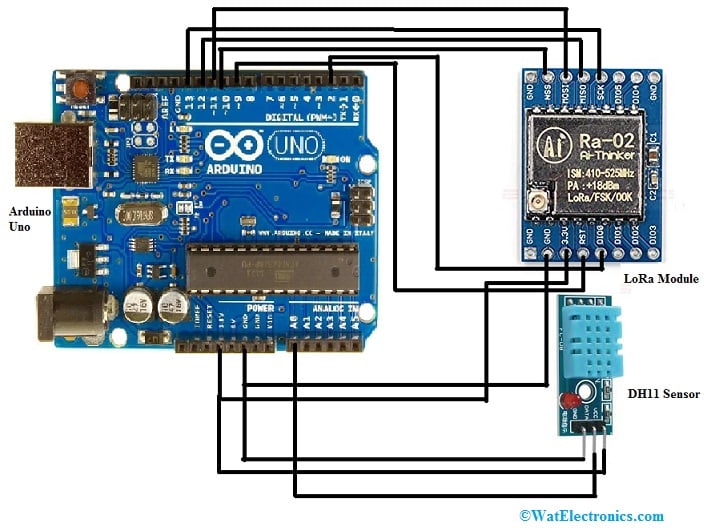
The interfacing of LoRa with the Arduino Uno and DHT11 sensor at the transmitting side is shown below. The LoRa module includes 16 pins where 6-pins are GPIO pins & 4-pins are GND pins. The connections of the LoRa SX1278 Module with the Arduino Uno board follow as;

Interfacing LoRa with Arduino UNO at Transmitting Side
- The 3.3V pin of the LoRa SX1278 Module is connected to the 3.3V of Arduino Uno board.
- The GND pin of the LoRa SX1278 Module is connected to the GND of the Arduino Uno board.
- The NSS pin of the LoRa SX1278 Module is connected to the D10 of the Arduino Uno board.
- The DIO0 pin of the LoRa SX1278 Module is connected to the D2 of the Arduino Uno board.
- The SCK pin of the LoRa SX1278 Module is connected to D13 of the Arduino Uno board.
- The MISO pin of the LoRa SX1278 Module is connected to the D12 of the Arduino Uno board.
- The MOSI pin of the LoRa SX1278 Module is connected to the D11 of the Arduino Uno board.
- The RST pin of the LoRa SX1278 Module is connected to the D9 of the Arduino Uno board.
- The connections of the DHT 11 Sensor with Arduino Uno board follow as;
- The VCC pin of the DHT11 sensor is connected to a 3.3V of Arduino Uno board.
- The GND pin of the DHT11 sensor is connected to the GND of the Arduino Uno board.
- The DATA pin of the DHT11 sensor is connected to A0 of the Arduino Uno board.
Interfacing LoRa with Arduino UNO at Receiving Side
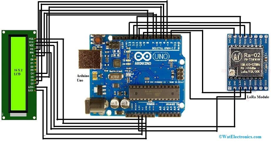
On receiving side, an Arduino Uno board with a LoRa module & 16×2 LCD Display is used. The interfacing of the Arduino Uno with LoRa & LCD is shown below. The connections of LoRa with Arduino UNO are the same as discussed in the transmitter section. So the connections of the LCD module with Arduino Uno board follow as;

Interfacing LoRa with Arduino UNO at Receiver Side
- The VSS pin of the LCD is connected to the GND pin of the Arduino Uno board.
- The VDD pin of the LCD is connected to the 5V pin of the Arduino Uno board.
- The VO pin of the LCD is connected to the GND pin of the Arduino Uno board.
- The RS pin of the LCD is connected to the D8 pin of the Arduino Uno board.
- The RW pin of the LCD is connected to the GND pin of the Arduino Uno board.
- The E pin of the LCD is connected to the D7 pin of the Arduino Uno board.
- The D4 pin of the LCD is connected to the D6 pin of the Arduino Uno board.
- The D5 pin of the LCD is connected to the D5 pin of the Arduino Uno board.
- The D6 pin of the LCD is connected to the D4 pin of the Arduino Uno board.
- The D7 pin of the LCD is connected to the D3 pin of the Arduino Uno board.
- The A pin of the LCD is connected to the 5V pin of the Arduino Uno board.
- The K pin of the LCD is connected to the GND pin of the Arduino Uno board.
Code
The complete Arduino code for the transmitter is given below.
#include <SPI.h>
#include <LoRa.h>
#include “DHT.h”
#define DHTPIN A0 // what pin we’re connected to
#define DHTTYPE DHT11 // DHT 11
DHT dht(DHTPIN, DHTTYPE);
int hum;
float temp; //Stores temperature value
int counter = 0;
void setup() {
Serial.begin(9600);
dht.begin();
while (!Serial);
Serial.println(“LoRa Sender”);
if (!LoRa.begin(433E6)) {
Serial.println(“Starting LoRa failed!”);
while (1);
}
}
void loop() {
temp = dht.readTemperature();
hum = dht.readHumidity();
Serial.print(“Sending packet: “);
Serial.println(counter);
// send packet
LoRa.beginPacket();
LoRa.print(“Humidity: “);
LoRa.print(hum);
LoRa.print(“c”);
LoRa.print(“Temperature:”);
LoRa.print(temp);
LoRa.endPacket();
counter++;
delay(5000);
}
The complete Arduino code for the receiver is given below.
#include <SPI.h>
#include <LoRa.h>
#include <LiquidCrystal.h>
const int rs = 8, en = 7, d4 = 6, d5 = 5, d6 = 4, d7 = 3; //Mention the pin number for LCD connection
LiquidCrystal lcd(rs, en, d4, d5, d6, d7);//Initialize LCD method
void setup() {
Serial.begin(9600);
lcd.begin(16, 2);
while (!Serial);
Serial.println(“LoRa Receiver”);
if (!LoRa.begin(433E6)) {
Serial.println(“Starting LoRa failed!”);
while (1);
}
}
void loop() {
// try to parse packet
int packetSize = LoRa.parsePacket();
if (packetSize) {
// received a paket
Serial.print(“Received packet ‘”);
// read packet
while (LoRa.available()) {
char incoming = (char)LoRa.read();
if (incoming == ‘c’)
{
lcd.setCursor(0, 1);
}
else
{
lcd.print(incoming);
}
}
}
Begin the program by simply including the necessary libraries & initializing all pins. Here, the SPI as well as LoRa library in this code is mainly utilized for the LoRa module.
In the function of void setup(), we start the serial monitor. Here, the LoRa operating frequency is 433 MHz. In the function of the void loop, we can calculate the values of temperature & humidity with the functions of DHT.readTemperature() & DHT.readHumidity() and start transmitting these values. On the receiver section, display those values on the 16×2 LCD. Here, the keyword “c” is used to inform the receiver to print the following data on the second line.
Thus, the temperature & humidity values are transmitted from one Arduino Uno board to other through the LoRa SX1278 module. Here at the transmitter section, the temperature & humidity values are received by Arduino from the DHT11 sensor. After that, it transmits it to the Arduino Uno board in the receiver section through the LoRa SX1278 module. Finally, temperature & humidity values will be displayed on LCD in the receiver.
Applications
The applications of an SX1278 are a Lora RF module includes the following.
- This module is used in every commercial product due to its long-range as well as successful operating capability.
- It is used in the agriculture field.
- This module is used in industries and IoT communication.
- The commercial meter communicates through this RF module.
- This SX1278 RF module is reliable in creating star and mesh topology networks
- It is used in IoT applications.
- This module is used in building and home automation.
- It is used in long-range communication.
- This module is used for Industrial controlling & monitoring.
Please refer to this link for ESP12E WiFi Module.
Please refer to this link for SX1278 LoRa RF Module Datasheet.
Thus, this is an overview of the SX1278 LoRa rf module – pin configuration, specifications, interfacing, and working with applications. Here is a question for you, what is LoRa Technology?