JFET is a 3-terminal semiconductor device that is used as amplifiers, voltage-controlled resistors, or electronically-controlled switches. Not like BJTs, these are completely voltage-controlled because they do not require a biasing current. There are various JFETs available in the market which are designed by different manufacturers. Similarly, 2N5457 N-channel JFET was manufactured by a semiconductor supplier company namely ON Semiconductor. They manufacture different products like logic, custom, discrete, signal management, and power devices, especially for consumer, automotive, industrial, communications, medical, aerospace, military, and LED lighting applications. So this article provides brief information about 2N5457 N-channel JFET like pin configuration, specifications, circuit, and its applications.
What is 2N5457 N-channel JFET?
The 2N5457 JFET is an N- Channel Depletion layer transistor that is broadly used in audio equipment for tone modulation, amplification & many other purposes. This JFET includes three terminals like source, drain, and gate. This JFET adopts the standard plug-in type of TO-92 & epoxy resin capsulation, so it has many mechanical benefits like lightweight, high gain, small size, solid shell, low power operation & good insulation so that it can be used in battery-operated devices. This JFET is appropriate for general-purpose switching & amplification-related applications.
Pin Configuration:
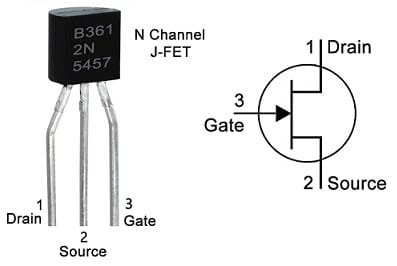
The pin configuration of 2N5457 N-channel JFET is shown below. This JFET includes three pins gate, source, and drain which are indicated with G, S & D.

2N5457 N-channel JFET PIn Configuration
- Pin1 (Drain): It is a Drain (D) pin of the JFET. The majority of charge carriers will exit from this pin.
- Pin2 (Source): It is a Source (S) pin of the JFET. The majority of charge carriers will enter through this pin.
- Pin3 (Gate): It is a Gate (G) pin of the JFET that controls the charge carrier’s flow from the source terminal to the drain.
Features & Specifications:
The features and specifications of 2N5457 N-channel JFET are discussed below.
- Both the drain & source terminals are Interchangeable.
- N−Channel used for Higher Gain.
- Input Impedance is High AC.
- Input Resistance is High DC.
- Low Transfer & Input Capacitance.
- The package is Plastic Encapsulated.
- Availability of Pb−Free Packages.
- Low Cross−Modulation &Intermodulation Distortion.
- Voltage from Drain to Source is (Vds) – 25Volts.
- Voltage from Drain to Gate is (Vdg) is 25Volts.
- Voltage from Gate to Source (Vds) is -25Volts.
- The Dissipation of Power is 310mW.
- Max Gate Current is 10mA.
- Cut-off voltage from Gate to Source is -0.5 to –6.0 Volts.
- Drain Current is 5.0mA.
- The type of Package is TO-92.
- N Channel Transistor.
- Max Temperature Range is from -55 to +150 C.
- Mount Style is – Through Hole.
- No.of Pins – 3.
- No. of Terminations – 3.
- Junction FET Technology.
- Height is 4.7mm.
- The width is 3.68mm.
- Transistor Application is Switching.
- The operating Mode is Depletion.
- Terminal Finish is Tin/Lead.
- Its Weight is 201mg.
2N5457 N-channel JFET as a Switch Circuit
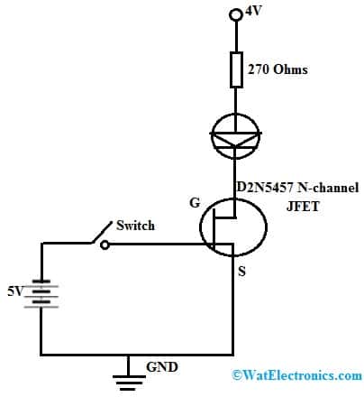
The circuit diagram of 2N5457 N-channel JFET as a switch is shown below. The required components to make this circuit mainly include a 2N5457 JFET, LED, 270 ohms resistor, and voltage source. Connect the circuit as per the circuit shown below.

2N5457 N-channel JFET as a Switch Circuit
Generally, this JFET normally turns ON at zero gate voltage, so it is a normally ON device. In addition, this transistor does not need any biasing voltage for the flow of current to supply from the drain (D) terminal to the source (S) terminal, then this transistor is in its saturation mode. So, once the voltage source is given to the LED & no voltage at the gate (G) terminal of the transistor, then the LED will glow. So as to turn off JFET, an adequate negative voltage must be provided to the gate (G) terminal of the JFET so that it enters into the cut-off mode. So there is no flow of current from drain (D) to source (S) terminals any longer & the LED will lose its glow. The resistor in this circuit is mainly used for limiting the flow of current throughout the LED to keep away from damage.
Equivalent & Replacement of 2N5457
The equivalent of 2N5457 JFET are; 2N4339, 2N4340, J201, 2N4338, 2N4341, NTE458, 2N5459, etc. The replacements of 2N5457 JFET are; J107, 2N5458, BF246B, J309, etc. Some equivalent JFET transistors’ pin configurations may differ, so need to verify their pin configuration before utilizing instead of 2N5457.
How to Long Run 2N5457 JFET Securely in a Circuit?
To obtain good performance with 2N5457 JFET, it is always recommended to stay under the highest ratings. Do not drive the load above 10mA and do not operate the load > 25V throughout this transistor, The drain (D) to gate (G) voltage shouldn’t increase from 25V, and reverse gate (G) to source (S) voltage should not be enhanced from -25V, This transistor should operate & store above -55 C & <+150 C.
Advantages
The advantages of 2N5457 N-channel JFET include the following.
- 2N5457 N−Channel JFET has many mechanical benefits like lightweight, available in small sizes, solid shell & good insulation.
- It is a famous JFET transistor available in the TO-92 package.
- It has high impedance.
- It consumes less power.
- These are designed in small sizes, so occupies very less space within circuits.
- This transistor has less noise & high gain.
- These are voltage-sensitive devices including high input impedance.
- These are mainly preferred above BJTs to utilize as the i/p stage to a multi-stage amplifier.
Where to Use/Applications:
The applications of 2N5457 N-channel JFET include the following.
- 2N5457 JFET is mainly used for amplification purposes thus it can be utilized in different low-level signals amplification whether it is audio or another kind of signal within electronics.
- This transistor can also be used as a switch.
- 2N5457 N-channel JFET is used in Audio Preamplifier & sensor circuits.
- These are used for the amplification of the low-level signal.
- These are used in audio amplifier stages, IR detection, amplifier system, audio modulation, small switching-based application, etc.
- These are used for tone controlling, noise generators, Tone control, amplifiers with less noise, phase-shifting oscillators, and current limiting systems.
Please refer to this for How to Select a Transistor.
Please refer to this link to know more about the 2N5457 N-channel JFET Datasheet.
Thus, this is an overview of a 2N5457 N-channel JFET – pin configuration, features, specifications, circuit, advantages, and applications. The 2N5457 N Channel JFET is a voltage control device, so that does not need any bias current to control the huge current on other terminals. This transistor is mostly designed for switching & audio applications. Here is a question for you, what is the function of a JFET?