An ADC or analog-to-digital converter or A-to-D or A/D in electronics is a system that changes the signal from an analog to a digital signal without changing its necessary content. An analog signal is a continuous signal in terms of both amplitude & time whereas a digital signal is discrete in terms of both time & amplitude. There are multiple ADC architectures but the most particular ADCs are implemented as ICs because of the complexity & the need for accurately matched components. There are various ADC modules available that are used based on requirements like ADC0804, MCP3008, MCP3008 ADC, ADC0808, and many more. This article discusses an overview of MCP3008 ADC – pin configuration, specifications, and its applications.
What is MCP3008 ADC?
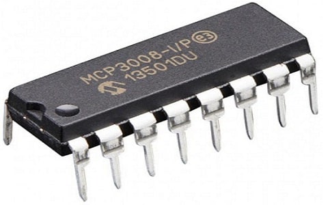
The MCP3008 is one of the most popular ADC IC used to combine high performance & low power consumption within a small package to make it perfect to use in embedded control applications. This ADC is a 10-bit ADC with 8 single-ended i/p channels. It includes a four-wire serial SPI-compatible interface, used to obtain digital output for all the channels. This IC includes an onboard sample & holds circuitry and provides both analog & digital ground connections which help reduce noise.

MCP3008 ADC
MCP3008 ADC Pin Configuration:
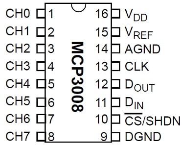
The pin configuration of the MCP3008 ADC is shown below. This IC includes 15 pins and each pin and its function are discussed below.

MCP3008 ADC Pin Configuration
Pins1,2,3,4,5,6,7 & 8 (Analog i/p pins): These eight input analog pins help in measuring the inbound analog voltage.
Pin9 (Digital Ground): It is connected to the GND of the circuit
Pin10 (CS/SHDN): It is a chip select/shutdown pin which is connected to MCU or GPIO pin to turn ON/OFF the IC.
Pin11 (DIN): A Serial Data In pin is used for SPI communication.
Pin12 (DOUT): It is a serial data out mainly used for SPI communication
Pin13 (CLK): It is a serial clock pin, used to provide a CLK signal for SPI communication.
Pin14 (AGND): It is an analog ground pin connected to the GND of the reference voltage
Pin15 (VREF): It is a reference voltage pin, connected to the reference voltage for ADC Conversion
Pin16 (VDD): This pin is used to provide positive (+Ve) voltage to the circuit.
Features and Specifications:
The features and specifications of MCP3008 ADC include the following.
- Manufactured by Microchip Technology
- Available in SOIC, TSSOP & PDIP packages
- The type of Mounting is Through Hole.
- The part number of the base is MCP3008.
- The number of bits -10.
- The sampling rate for each sec is 200k.
- The type of input is Pseudo differential single ended
- SPI data interface.
- MUX-S/H-ADC configuration.
- SAR architecture.
- Analog voltage supply ranges from 2.7V to 5.5V.
- Digital voltage supply ranges from 2.7V to 5.5V.
- The operating temperature ranges from -40 °C to 85°C.
- Programmable analog inputs as single-ended otherwise pseudo differential pairs.
- On-chip sample & hold circuitry.
Equivalent & Alternative MCP3008 ADCs
The equivalent MCP3008 ADC is PCF8591 and alternative ADC ICs are ADC0804, ADC0808, and ADS11115.
MCP3008 ADC Interfacing with Raspberry Pi & Potentiometer
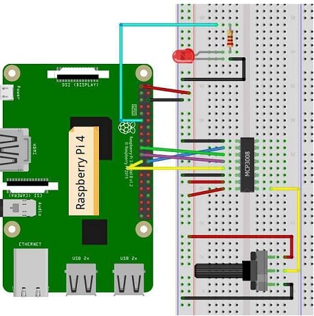
The interfacing of MCP3008 ADC with Raspberry Pi & Potentiometer is shown below. This interfacing is mainly used for reading analog signals through Raspberry Pi to control LED brightness.
The required components for this interfacing mainly include; Breadboard, Jumper Wires, Raspberry pi 4, MCP3008 ADC, Potentiometerp-5K/10K, Resistor – 220 ohms, and LED.
Generally, a potentiometer is used for different purposes like fan speed controlling, radio volume controlling, light brightness controlling, and many more. Potentiometer has an adjustable knob to adjust the resistance & thus changes in current. Here, a potentiometer is used with raspberry pi.
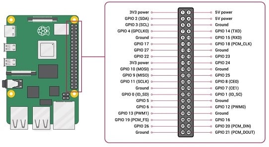
In Raspberry pi, the GPIO pins can read only digital signals, either LOW or HIGH (3.3V). It cannot provide values in between 1V, 1.5V, 2V, etc. Thus, we have to change the signal from analog to digital through an ADC chip. So here we are using the MCP3008 ADC chip to convert this signal. This ADC chip includes 16 pins where 8 pins are for analog inputs,& 8- pins are used for raspberry pi GPIOs.

Raspberry pi 4 Pin Configuration
First, we need to enable SPI, for that go to MENU => Preferences => Raspberry pi configuration => Enable SPI.
To control the LED brightness, take the potentiometer values through MCP3008 ADC & give them to PWM GPIO.
The connections of this MCP3008 ADC interfacing with Raspberry Pi & Potentiometer for controlling LED brightness follow as;

MCP3008 ADC Interfacing with Raspberry Pi
The potentiometer VCC pin is connected to the 3V3 power pin of the raspberry pi
The potentiometer GND pin is connected to the GND pin of the raspberry pi and
The potentiometer middle lead-like output pin is connected to pin1 of MCP3008 ADC.
The pin9 of MCP3008 is connected to the GND pin of the Raspberry Pi.
The pin10 of MCP3008 is connected to the GPIO8 pin of the Raspberry Pi.
The pin11 of MCP3008 is connected to the GPIO10 pin of the Raspberry Pi.
The pin12 of MCP3008 is connected to the GPIO9 pin of the Raspberry Pi.
The pin13 of MCP3008 is connected to the GPIO11 pin of the Raspberry Pi.
The pin14 of MCP3008 is connected to the GND pin of the Raspberry Pi.
The pin15 of MCP3008 is connected to the 3.3V pin of the Raspberry Pi.
The pin16 of MCP3008 is connected to the 3.3V pin of the Raspberry Pi.
The positive terminal of the LED is connected to pin11 like GPIO17 of Raspberry Pi and the negative terminal of the LED is connected to pin6 like the GND pin of Raspberry Pi
Python Code for LED Brightness Controlling:
from gpiozero import PWMLED, MCP3008
from time import sleep
pot = MCP3008(0)
led = PWMLED(17)
while True:
if (pot.value < 0.002):
led.value = 0
else:
led.value = pot.value
print(pot.value)
sleep(0.1)
In the above code from gpiozero import PWMLED and MCP3008, first, we have to import PWMLED & MCP3008 using gpiozero library. We are using an ADC chip like MCP3008 & LED controlling is done with PWM.
Now we need to import sleep from time because when we desire to pause otherwise hold the process for a specific amount of time.
Creating an object-like pot that refers to MCP3008 ADC Pin 1 is channel 0 within MCP3008.
Creating the object of PWMLED known as LED that refers to pin11 like GPIO 17.
This code will run within a loop forever.
The current reading value of the potentiometer is accessed by pot. value, if this value is below 0.002 then the LED will turn OFF. This value can be modified much lower. However, some manufacturing or electrical faults are also there, which cannot allow it total zero.
else it will modify LED brightness based on the value of the potentiometer.
Need to print the value of the potentiometer in each 0.1 Sec.
Advantages of MCP3008 ADC
The advantages of MCP3008 ADC include the following.
- MCP3008 ADC is ideal to utilize within embedded systems-based applications.
- This ADC includes an interface compatible with a 4-wire serial SPI that is mainly used for obtaining digital o/p for all channels.
- It includes an onboard sample & hold (S&H) circuitry and it provides both analog & digital ground connections to help in the reduction of noise.
- The precision of this ADC is quite related to Arduino Uno.
- This IC is an excellent option, to begin with, ADC circuits.
- This ADC has good precision.
- This IC is programmable, so it provides 4 pseudo-differential i/p pairs or 8 single-ended i/ps.
- It is a low-cost analog-to-digital converter.
- It is very famous for Raspberry Pi as Analog input IC.
Where to Use/Applications
The applications of MCP3008 ADC are discussed below.
- MCP3008 ADCs are used in Raspberry pi boards for analog-to-digital conversion. This chip simply utilizes an SPI interface for communication. In this board, simply 4 GPIO pins are necessary thus, you can obtain 8 extra analog inputs with this IC.
- The MCP3008 ADC converts these signals from analog to digital.
- Sensors utilize analog outputs so; various devices require these converters to read these outputs.
- These converters are used in multi-channel data loggers, data acquisition, industrial PCs, robotics, motor control, smart sensors, industrial automation, home medical, portable instrumentation, instrumentation & measurement applications.
Please refer to this link to know more about MCP3008 ADC Datasheet.
Thus, this is an overview of MCP3008 ADC – features, specifications, pin configuration & its applications. This MCP3008 ADC is a 10-bit programmable converter with 8 input channels. Thus, it is necessary for embedded systems applications. Here is a question for you, what is ADC?