In electrical systems, the AC current sensors or current transformer sensors are simple and affordable devices used to monitor performance and efficiency and generate analog output signals. These are real-time current monitoring devices that can predict component failures, reduce downtime, and plan preventive maintenance. There are different types of current sensors used in industrial equipment, voltage, and current measurements, ADC circuits, household equipment, data acquisition systems, etc. Among many, this article gives a brief description of the Pin configuration, working, and technical features of the ZMCT103C high Precision current sensor that is used to measure the AC current with current transformer using the magnetic-field technique.
What is ZMCT103C Precision Current Sensor?
The ZMCT103C is a precision microcurrent current transformer sensor module, which can measure up to 5 Amps of AC current. It comes with 4 output pins and is available in epoxy encapsulation. It detects and generates the analog output signals proportional to the AC current flowing via the wire. The generated output signal which is either DC current or AC current can be displayed by using either an ammeter or control/monitoring system in digital form.
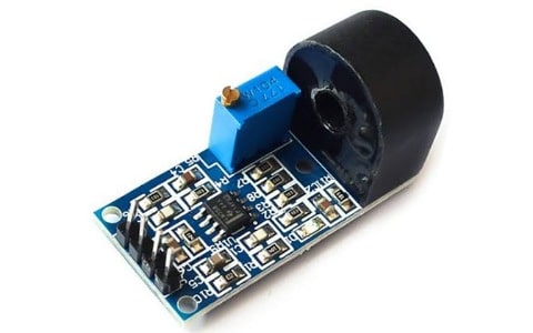
ZMCT103C Precision Current Sensor
This sensor works on the principle of change in the magnetic field between the two coils and generates low noise and accurate analog signals that are proportional to the AC or DC input current. It is a fully integrated Hall-effect current sensor module used in industrial applications and DIY projects where the accurate and low-noise AC current needs to be measured. These current transformer sensors are widely used in HEV inverters, overload detection circuits, electronic servo control systems, industrial and consumer inverters, and tripping and underload circuits.
Pin Configuration
The ZMCT103C module is a highly accurate microcurrent precision current sensor with a 5 mA rated output current at 5A. It comes with 4 output pins with epoxy encapsulation. The pin configuration of ZMCT103C is given below.
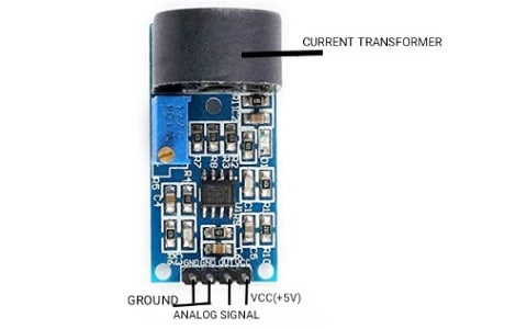
Pin Configuration of ZMCT103C
- Pin 1 & 2: Ground: There are 2 ground pins used for common ground connection.
- Pin 3: Analog Signal: This pin refers to the generated analog output signal proportional to the current flowing through the wire.
- Pin 4: VCC(+5V): This pin refers to the positive power supply of +5V.
Technical Features and Specifications of ZMCT103C Precision Current Sensor:
The following are the technical features and specifications of the ZMCT103C precision current sensor.
- It is a small module with epoxy encapsulation that can measure precise current and power with high accuracy.
- Has an Onboard microcurrent precision transformer, sampling resistor, and potentiometer.
- The ratio of current is 5 Amp:5 mAmps. A
- The maximum primary current is 20A @50/60Hz.
- Rated primary current is 5A @ 50/60Hz.
- The input current range is 0-10 Amps @50 ohms.
- The rated output current is 5 mAmps @5 Amps of input current.
- Turns ratio of the transformer is 1000:1. (Np:Ns).
- The isolation voltage is 4500 volts.
- Installed on PCB.
- DC resistance of winding is 155 ohms @20°C.
- The accuracy class is 0.2.
- Linearity is ≤0.2%.
- Phase angle error is ≤15 @ input = 5 Amps and sampling resistor 50 ohms.
- The permissible error is -0. 2%≤f≤+0.2% @ 5A and 50 ohms.
- The operating temperature range is -40°C to +85°C.
- Works as a precision current transformer sensor and over-current protection sensor.
- The secondary coil pin length is >3mm.
Construction and Working Of ZMCT103C:
The ZMCT103C high-precision current sensor is designed in an epoxy-coated donut-shaped module in which the secondary (Ns) winding is wound around a ferrite bead. The primary coil in the module is the wire through which the current is measured and is passed through the donut hole of the module. The changing magnetic field produces the desired result. The accuracy of the measurement of the device can be enhanced by increasing the no. of turns in the primary winding/coil. The basic construction of the ZMCT103C module is shown in the figure below.
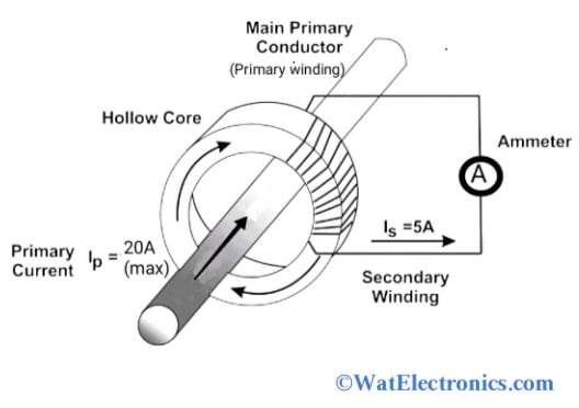
Construction of ZMCT103C
The ZMCT103C microcurrent precision current sensor module works on the principle of change in the magnetic field induced between the secondary and primary windings of the module as shown in the figure above. The basic circuit diagram shown below helps to understand the working of the module.
This module consists of a donut-shaped ZMCT103C IC, in which secondary winding acts as a current transformer used to sense and measure the current flowing in the wire. It also contains an operational amplifier (op-07) along with the sampling resistor connected to the module as shown in the circuit diagram. The purpose of the sampling resistor is to reduce power consumption and avoid short circuits that might damage the components of the module.
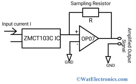
Basic Circuit Diagram Of ZMCT103C
When the input AC current signal is given, the current transformer in the module monitors and measures the current flow. Finally, the output signal generated by the current transformer is amplified by the op-07. Here the amplification factor can be adjusted by using the in-built potentiometer of the ZMCT103C module. The output voltage signal generated by the module is accurate, low noise signal, and also directly proportional to the given AC current signal.
Interfacing ZMCT103C With Arduino UNO:
The ZMCT103C is also referred to as an AC current transformer sensor with high precision current used to monitor and measure the current of up to 5 Amps in several applications. By connecting this module to the microcontroller or Arduino UNO we can easily measure the output AC voltage proportional to the current flowing in the wire (that passes via the hole of the ZMCT103C IC). Now let’s know how to interface the ZMCT103C module with the Arduino UNO board. The interfacing diagram is shown below.
The components required are;
- Arduino UNO
- ZMCT103C module.
- Jumper wires
- Arduino IDE Software for Coding
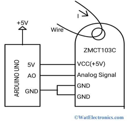
Interfacing ZMCT103C Module With Arduino UNO
From the above figure, the VCC(+5V) pin of the ZMCT103C module is connected to the 5V pin of the Arduino UNO. Now shorten the two ground pins of the module and connect to the GND pin of the Arduino UNO. To observe the output signal of the module connect the analog signal pin to the AO pin of the Arduino UNO. To measure the output current, insert the signal wire through the hole of the ZMCT103C module. Upload the Arduino code as given below and open the serial monitor to observe the output at different voltage ranges.
Code:
#define calibration_const 355.55
int max_val;
int new_val=0;
int old_val = 0;
float rms;
float IRMS;
void setup() {
pinMode(A0,INPUT);
Serial.begin(9600);
}
void loop() {
new_val = analogRead(A0);
if(new_val > old_val) {
old_val = new_val;
}
else {
delayMicroseconds(50);
new_val = analogRead(A0);
if(new_val < old_val) {
max_val = old_val;
old_val = 0;
}
rms = max_val * 5.00 * 0.707 / 1024;
IRMS = rms * calibration_const;
Serial.print(” IRMS: “);
Serial.println(IRMS);
delay(1000);
}
}
Working:
Firstly calibrate the ZMCT103C module by calculating the AC output voltage for the already-known current value. From this, the calibration factor is calculated easily. This factor changes by turning the onboard potentiometer on the module. For this, the signal wire whose current is to be determined is inserted through the hole of the module. And then connect the VCC and GND pins of the module to the 5-30V DC power supply pins. And connect the Analog signal (VOUT) and GND pins to the oscilloscope. Observe the generated output waveform and change in voltage/amplitude on the oscilloscope by turning the potentiometer on the module. The increase in current should not exceed the value of 1/2 VCC otherwise the module gets damaged.
From the above code, the A0 pin of the Arduino is used to monitor the output analog voltage. Then, the RMS value of the current (in mA) flowing through the wire is determined by calculating the maximum voltage at different ranges. The current flowing through the wires is also measured at the soldering station to check if the code is working.
Applications
A few applications of the ZMCT103C microcurrent precision current sensor are given below.
- In electrical energy meters.
- Ground fault detection circuits.
- Household electrical appliances.
- Measurement of AC voltage.
- Industrial applications.
- Relay protection circuits.
- Electrical testing equipment.
- ADC circuits.
- Overload current sensing.
Know more about Magnetic Sensor.
Please refer to this link for ZMCT103C Precision Current Sensor Datasheet
Thus, this is all about an overview of the ZMCT103C microcurrent precision current sensor. The alternatives of this module with different current ratios are ACS712, WCS1700, GY712, CJMCU 219, and ACHS 7123. By using a series of small ZMCT series microcurrent current transformers (high-precision) and op-amp circuits, we can design micro-current transformer modules for signal compensation, over-current protection, accurate sampling, and AC current signal acquisition within 5A.