In the 1970s, the technology of the LED introduced different types of Opto-isolators to attain maximum data transfer rate, monitor interruptions, and perform sensing of non-contact objects. These are employed in robotics and automation applications to monitor the exact inclination and position in robotics. Among many optoisolators, the MOC7811 encoder sensor or a slotted coupler module is developed with top-mounted emitter and receiver sections in a molded housing to monitor the wheel’s position in motors, monitor interruptions, computer printers, robotics, etc. This article gives a brief description of the features, pin configuration, and working of the MOC7811 encoder sensor.
What is the MOC7811 Encoder Sensor?
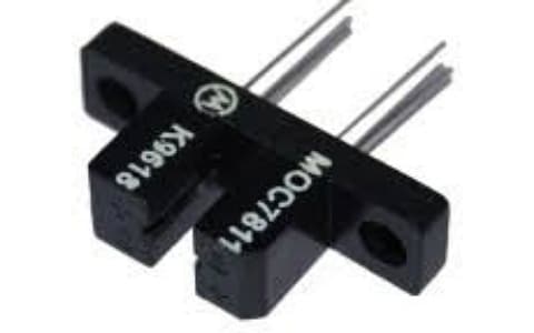
The MOC7811 is an Encoder sensor or slotted coupler module or Photointerrupter Or Opto-interrupter used to monitor the interruptions. It comes with a top-mounted transmitter and receiver sections in a plastic molded housing. It consists of the Infrared Light Emitting diode in the transmitter section and the phototransistor in the receiving section aligned facing each other in a single molded plastic package. It is available in 4-pin in 354 and 354A cases. It is mainly used in designing optical limit switches and rotary encoders at low cost. These are mainly used as switches to monitor the ON and OFF of the signals, monitor interruptions, and position of DC motors and robots. It is used to monitor interruptions due to non-contact objects. These sensors are very sensitive and available at affordable rates.

MOC7811 Encoder Sensor
Working of MOC7811 Encoder Sensor:
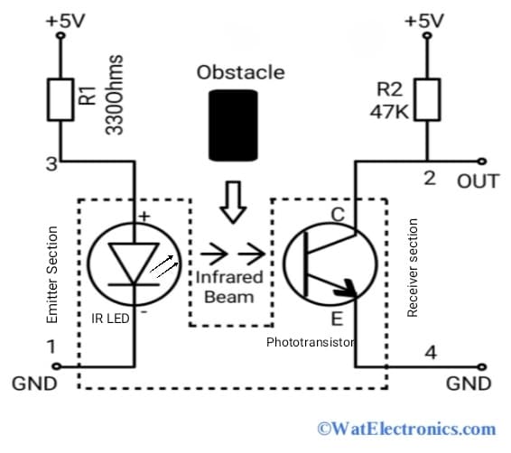
The MOC7811 is the encoder sensor module that uses light to transfer the incoming electrical signals between the two separate circuits. These can prevent the high voltages to protect the receiving section from damage. Consider the circuit diagram shown below to understand the working of the MOC7811 Encoder Sensor. The current limiting resistors R1 and R2 are used to prevent circuit damage from high voltages.

MOC7811 Encoder Sensor Circuit Diagram
From the above circuit diagram, Infrared LED is mounted in the emitter section and the NPN phototransistor is mounted on the other end of the plastic molding (receiver section). The IR LED converts the incoming electrical signal into a light signal. Then photodetector/phototransistor detects the Infrared beam/radiations emitted by the IR LED. The photodetector produces the output based on the light received by it and generates the output digitally.
A slot in the housing between the emitter and the detector provides a means of interrupting the signal. If any interruption occurs due to obstacles (non-contact objects) between the IR LED and Photodetector, the output will be 0 otherwise it will be 1. This change in output can be determined by using any microcontroller or Arduino or simple hardware circuit.
The logic level of the photodiode changes when the light emitted by the infrared LED is blocked by the intersecting gap of the encoder disk. These changes at this logic level can be detected by the discrete hardware or microcontroller. These sensors are mainly used to monitor the position feedback of the robots or limit switches.
Pin Configuration of MOC7811:
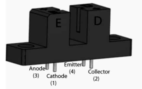
The MOC7811 is an encoder sensor module with an IR light-emitting diode and a phototransistor. It is used to sense non-contact optical objects. The IR LED and the phototransistor of the module are top-mounted facing each other and enclosed on a single plastic molded package as shown in the below schematic diagram. The IR LED acts as an IR transmitter and the phototransistor is normally an NPN transistor. It works as a position encoder sensor or limit switch to monitor the wheel’s position. The pin configuration of the MOC7811 encoder sensor is shown in the figure below.

Pin Configuration Of MOC7811
Cathode: This pin refers to the cathode terminal (negative terminal) of the Infrared light-emitting diode mounted on the emitter section of the module. It works as a ground pin
Collector: This pin refers to the collector terminal of the NPN phototransistor/photodetector, which is mounted on the receiving section of the module. The output is generated from this pin.
Anode: This pin refers to the anode terminal (positive terminal) of the internal IR LED of the MOC7811 module. It receives the incoming signal.
Emitter: This pin refers to the emitter terminal of the phototransistor Or photodetector of the MOC7811 module. It works as a ground pin.
Features and Technical Specifications:
The features and technical specifications of the MOC7811 are given below.
- It is an Encoder sensor module with IR LED and a phototransistor molded in a plastic case.
- The input Voltage is 5V.
- The minimum current transfer ratio (CTR) is 5% at forward current IF = 20mA and VEC=5V.
- Maximum collector to emitter voltage VCE(sat) = 0.4V @ If = 30mA.
- Collector current Ic= 1.8mA.
- Maximum Forward voltage Vf = 1.8V @ IF = 50mA.
- Typical Ontime and the offtime ratio of the PWM Ton/Toff = 12/60 microseconds @ VCC = 5V, RL = 2.5-kilo ohms, IF=30mA.
- The current limit is 50mA.
- Transistor output voltage VCEo = 30V.
- Offtime of the PWM Toff = 60 micro sec.
- Available in 354 and 354A cases.
- The diameter of the mounting hole is 3mm.
- The spacing of the mounting hole is 19mm.
- The slot depth is 7mm.
- The slot width is 3mm.
Interfacing MOC7811 Encoder Sensor with Arduino UNO:
In speed testing of DC motors, the PWM signal is given to the motor to measure its actual RPM and duty cycle. As the width of the PWM signal varies, the motor’s speed also varies and its duty cycle changes from minimum to maximum. At the same, the speed variation at the different applied voltage signals is also monitored and measured. In this application, to calculate these parameters like the width of the PWM signal (in %), applied voltage value, and speed of the motor in RPM, we use an Arduino UNO board and the encoder sensor module MOC7811 as the main components. Here, an Arduino UNO is used to generate PWM signals, and the Opto-interrupter measures the speed variation of the motor in RPM. The result is displayed on a 16×4 LCD.
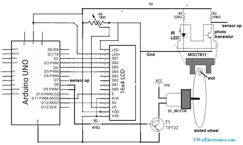
The interfacing diagram of MOC7811 with Arduino UNO to test the speed of the DC motor is shown in the figure below. The components required for this project are;
- Arduino UNO board
- MOC7811 Encoder sensor.
- TIP122 NPN Darlington Transistor
- 16×4 LCD
- Current limiting resistors.
- 12V DC motor.
- Connecting wires.

From the above diagram, the Arduino analog output on pin 9 controls/drives a 12V DC motor at 2000 RPM via the TIP122 NPN Darlington transistor. This analog output pin 9 is connected to the base terminal of the TIP122 through the R2 current limiting resistor of 470 ohms and the 12VDC motor is connected to the collector of the TIP122. The internal IR LED of the MOC7811 is supplied with a 5V supply in forward bias from the 5V pin of the Arduino UNO board through another R1 current-limiting resistor of 220 ohms.
The internal phototransistor of MOC7811 is pulled up by an R2 resistor of 10 kiloohms. The collector output (MOC7811 sensor output) of the transistor in MOC7811 is connected to digital pin 7 of the Arduino UNO. The 16×4 LCD data pins D4, D5, D6, and D7 are connected to Arduino digital pins D5 PWM, D4, D3 PWM, and D2. While the RS and E control pins of 16×4 LCD are connected to Arduino’s pins D12 and D11.
The R/W, VSS, and LED- pins of the 16×4 LCD are connected to the GND pin of the Arduino board. The VCC and the LED+ pins of the 16×4 LCD are connected to the 5V pin of the Arduino board. The VO pin of the LCD is connected to the variable 10-kilo ohms resistor R3 to change the contrast of the LCD.
The other terminal of the DC motor is connected to 12V VCC. External power supply is used to give the 12V supply to the motor. And power up the Arduino UNO board and the Opto-interrupter MOC7811 by using a USB from a laptop/computer. Attach the slotted wheel to the shaft of the motor and fix the MOC7811 sensor in a place where the slotted wheel can pass through the sensor’s air gap as shown in the above diagram. The 16×4 LCD will display the output parameters (Voltage, speed, and rpm).
The Arduino code for interfacing MOC7811 Encoder Sensor with Arduino UNO
###
#include <LiquidCrystal.h>
LiquidCrystal lcd(12, 11, 5, 4, 3, 2);
#define pwm_ip 8
#define rps_ip 7
int ontime,offtime,duty,pw=255,rps,rpm;
float volt,period;
long int rps_Ton,rps_Toff,rps_time;
void setup()
{
pinMode(pwm_ip,INPUT);
pinMode(rps_ip,INPUT);
lcd.begin(16, 4);
lcd.clear();
lcd.print(“PWM_ip:255”);
lcd.setCursor(0,1);
lcd.print(“PWM_duty:100%”);
lcd.setCursor(0,2);
lcd.print(“PWM_volt:12.00”);
lcd.setCursor(0,3);
lcd.print(“speed:”);
}
void loop()
{
for(pw=250;pw>100;pw-=15) // decrease the pulse width by 2%
{
analogWrite(9,pw); // generate PWM
delay(7000); // apply delay for motor to attain full speed
ontime = pulseIn(pwm_ip,HIGH); // measure ON time of PWM
offtime = pulseIn(pwm_ip,LOW); // measure OFF time of PWM
period = ontime+offtime; // calculate total PWM time
duty = (ontime/period)*100; // calculate % pulse width
volt = 0.12*duty; // calculate applied motor voltage
rps_Ton = pulseIn(rps_ip,HIGH); // calculate ON time of RPS pulse input
rps_Toff = pulseIn(rps_ip,LOW); // calculate OFF time or RPS pulse
rps_time = rps_Ton+rps_Toff; // calculate total time
rps = 1000000/rps_time; // calculate frequency that is RPS
rpm = 60*rps; // calculate RPM from RPS
lcd.setCursor(7,0); // display all the values
lcd.print(pw);
lcd.setCursor(9,1);
lcd.print(duty);
lcd.print(‘%’);
lcd.setCursor(9,2);
lcd.print(volt);
lcd.print(‘v’);
lcd.setCursor(6,3);
lcd.print(rpm);
lcd.print(” RPM”);
}
for(pw=100;pw<250;pw+=15) // increase the pulse width and
{
analogWrite(9,pw); // do same as above
delay(7000);
ontime = pulseIn(pulse_ip,HIGH);
offtime = pulseIn(pulse_ip,LOW);
period = ontime+offtime;
duty = (ontime/period)*100;
volt = 0.12*duty;
rps_Ton = pulseIn(rps_ip,HIGH);
rps_Toff = pulseIn(rps_ip,LOW);
rps_time = rps_Ton+rps_Toff;
rps_time = rps_Ton+rps_Toff;
rps = 1000000/rps_time;
rpm = 60*rps;
lcd.setCursor(7,0);
lcd.print(pw);
lcd.setCursor(9,1);
lcd.print(duty);
lcd.print(‘%’);
lcd.setCursor(9,2);
lcd.print(volt);
lcd.print(‘v’);
lcd.setCursor(6,3);
lcd.print(rpm);
lcd.print(” RPM”);
}
}
###
Working:
When the PWM signal of maximum pulse width is applied to the Motor from the Arduino, then the motor rotates at a maximum speed and the slotted wheel also rotates. To attain full speed, a delay is provided. On completion of one full revolution by the motor, the slotted wheel moves through the air gap of the MOC7811. sensor. The IR light falls on the MOC7811 sensor’s internal phototransistor due to the movement of the rotating slotted wheel through the air gap. Then the phototransistor starts conducting and generates negative pulses as PWM output at its collector terminal. One negative pulse is generated on each revolution of the motor.
To calculate these pulses’ frequency, the ON time (Ton) and the OFF time (Toff) need to be measured. Since the frequency of these pulses is nothing but revolutions per second (RPS) of the motor.
So, time period = Ton + Toff (in microseconds)
Frequency = (1000000 / Time period) in Hz.
The formula to calculate the motor speed in RPM from its RPS,
RPM = 60 x RPS
The PWM input signal varies from 250 to 100 in 15 steps and is displayed on the LCD screen directly.
The duty cycle of the PWM output is obtained from the below formula,
PWM Duty cycle = {PWM_Ton / (PWM_Ton + PWM_Toff) } x 100
Where PWM_Ton = Ontime of the PWM output
PWM_Toff = Off time of the PWM output.
The applied voltage to the motor is calculated by using the formula,
Applied voltage to the motor = voltage of the motor x duty cycle.
Applied voltage = (12/100) x Duty cycle.
Therefore by decreasing (250 to 100) and increasing (100 to 250) the PWM input, the speed of the motor also decreases and increases continuously. Finally, the speed change in the motor rotation is observed from the PWM RPM output (speed) displayed on the LCD. And also the change in pulse width of the PWM and applied voltage of the motor is measured and displayed on the LCD accurately. Observe the RPM values (speed change of the motor) at different voltages and pulse width of the PWM.
Applications of MOC7811 Encoder Sensor:
A few applications of MOC7811 Encoder Sensor are,
- Monitor any interruptions.
- Measures Rotations Per Minute (RPM) of motors
- As smoke sensor
- In 3D printers, computer printers, and plotters
- In CNC machines
- Used in controlling or monitoring DC motor position or velocity
- Velocity and position servomechanisms.
- Factory automation robots
- Numerically controlled machines
- Used as a limit switch or non-contact optical switch.
Know more about Current Sensor.
Please refer to this link to know more about MOC7811 Encoder Sensor Datasheet.
Thus, this is all about an overview of the MOC7811 Encoder Sensor. The alternatives of this sensor are M274, OE-37, PC 817, MCT2E MOC7812, MOC7813, MOC7821, MOC7822, and MOC7823. To monitor any interruption with the MOC7811 encoder sensor, it is necessary to use a current limiting resistor before the emitter terminal of the internal phototransistor. Because these modules are very sensitive and get damaged very easily. These modules are non-contact optical switches/non-contact object sensing modules with improved reliability.