In many electronic circuits like small signal amplifier circuits, switching circuits, transfer circuits, etc. Junction Field Effect Transistors (JFETs) are commonly used electronic components due to their high input impedance and low power consumption. It is a voltage-controlled resistor and it is very easy to operate in low amplifier circuits in TV or radio receivers, modulation circuits like FM, AM, SW (Short Wave), etc. Among many, let’s discuss MPF102 N-channel JFET is affordable and rarely used in pre-amplifier circuits, antenna amplifier circuits, RF and VHF amplifier circuits. This article gives a brief description of the working of MPF102 N-channel RF or VHF amplifier JFET.
What is MPF102 JFET?
The MPF102 is an N-channel Junction Field Effect Transistor (JFET) VHF/RF amplifier used in electronic switching and low amplifier circuits. It is a voltage-controlled resistor that works in depletion mode. These are no longer manufactured and are also not recommended in new designs. But it is designed in equivalent forms as NTE457 and J113 JFETs.

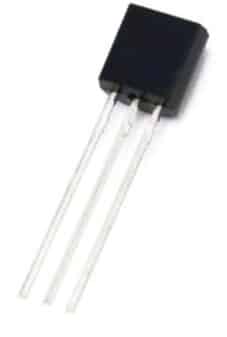
MPF102 JFET
Pin Configuration of MPF102 JFET:
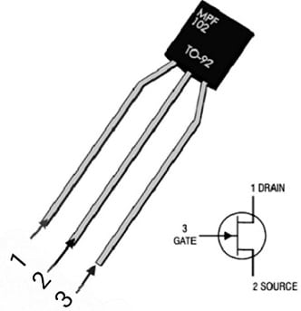
The MPF102 N-channel JFET is a 3-pin/terminal voltage-controlled FET available in the TO-92-3 package used in amplifier applications and general-purpose applications. The pin diagram of MPF102 N-channel JFET is shown in the figure below.

MPF102 JFET Pin Configuration
- Gate: This terminal is used to control the biassing of the N-channel JFET
- Source: This terminal is connected to the ground and controls the current flowing out through the pin.
- Drain: This terminal is used to control the flowing into the circuit through the drain. The majority of the charge carriers (electrons) move from the source to the drain terminal.
Features and Technical Specifications of MPF102 JFET:
The following are the features and specifications of MPF102 N-channel JFET:
- It is a general-purpose N-channel JFET that works in depletion mode and is available in TO-92-3 and Pb-free packages.
- The maximum drain to source voltage VDS is 25V.
- The maximum drain to source current IDC at VGS=0 is 2mAmps to 20mAmps.
- The continuous drain current is 10mAmps.
- The maximum power dissipation is 350mWatts.
- The range of storage temperature is -65°C to +150°C.
- The maximum junction temperature is +125°C.
- The negative gate-to-source voltage VGS for biasing is -7.5V.
- The maximum gate current IDC is 20mAmps.
- Input capacitance is 7pF.
- The reverse transfer capacitance is 3pF.
Working of MPF102 N-channel JFET:
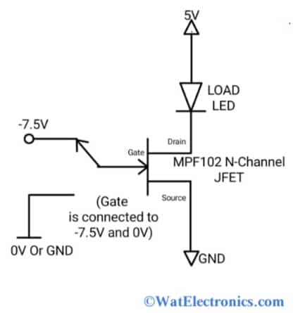
The MPF102 N-channel JFET is used as a voltage-controlled resistor, amplifier and electronic switch. As this is an N-channel JFET, the majority of charge carriers for current conduction are electrons. These are also called depletion mode devices and common source N-channel JFET amplifiers. The basic circuit diagram shown below explains the working of N-channel JFET. The components required are;

Basic Circuit Diagram of MPF102 JFET
- LED which acts as a load.
- MPF102 JFET
- -7. 5V for biasing
- 5V power supply.
From the above figure, the load LED is connected to the drain terminal of MPF102. As this is an N-channel JFET, the source terminal is grounded. The gate terminal is for controlling the biassing.
By default, the MPF102 is in an ON state and the current flows from the drain terminal to the source terminal due to the moment of majority charge carriers (electrons).
When the gate terminal is grounded (connected to 0V) the current starts flowing from the drain terminal to the source terminal and results in turning ON the LED (blinks). When the negative biassing voltage -7. 5V is applied to its gate terminal it turns OFF the LED. That means there is no current flow from the drain to the source terminal and the current flows out through the source terminal (which is connected to the ground).
At gate voltage =0V, the resistance is zero, and the current conduction of JFET is high. At gate voltage=-7.5V, the resistance increases and the current conduction decreases. That means the MPF102 JFET blocks the moment of charge carriers from the drain to the source terminal to stop the current flow. The condition in which no current flow occurs through the N-channel MPF102 JFET is called the pinched-off condition. In this state, it works as a resistor, and the source-to-gate voltage VGS controls the current.
Simple Active Antenna Amplifier Circuit for FM/AM/SW/MW Using MPF102 JFET:
In this section, let’s know how to design FM, AM, SW (short wave) MW (medium wave), and HF (High-Frequency) antenna amplifier circuits using an MPF102 N-channel JFET. This amplifier circuit is used in places where the weak signals are received and to amplify these signals at the antennas with equal input and output impedances. That means the impedance of the input signal is similar to the impedance of the output signal (amplified signal).
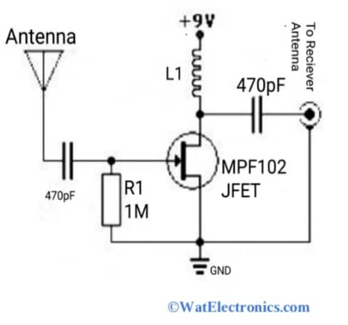
This simple and best antenna amplifier circuit can significantly amplify radio signals received by the TV or radio transmitting/receiving antennas. The circuit diagram of an antenna amplifier circuit using MPF102 N-channel JFET is shown in the figure below. The components required are,
- MPF102 N-channel JFET.
- Capacitors 470pF – 2.
- Inductor.
- Resistor 1 Mega Ohms.
- 9VDC Or 12VDC.

Simple Active Antenna Amplifier Circuit Using MPF102 JFET
The circuit diagram shown above works as an FM, MW, AM, and HF antenna amplifier circuit, simply called a pre-amplifier circuit which amplifies the received weak signals. This circuit is simple and easy to build using only one MPF102 transistor or NTE451 Or J113 JFETs. and a few other parts. The main component or heart of this active antenna amplifier circuit is MPF102 N-channel JFET due to its high input impedance and low noise.
This is extensively used in audio noise cancellation circuits and preamplifier circuits. Because the current flow through the source to drain (the reverse direction) doesn’t affect the circuit’s operation and the overall performance is excellent.
This simple AM/FM/SW active antenna circuit is designed for AM, FM and shortwave (SW) signal amplification and in radio receivers with an antenna height of 20-30 feet wire. The L1 for AM is 470microHenry and 20microHenry for SW (Short Wave). This L1 acts as an RFC (Radio Frequency Choke) for amplifying low-frequency signals at a particular frequency band. It is used to amplify the signals at lower frequency ranges.
The capacitor 470pF is to reduce the noise in signals. The entire circuit is powered with a 9VDC Or 12VDC power supply. The MPF102 N-channel JFET operates and helps to amplify the signals without using any biassing current. To cancel or reduce the noise in the received signals, bypass the power supply 9VDC with a 470pF capacitor as shown in the circuit diagram. The active antenna in the above circuit is either a copper wire or bus bar or piano wire or 18-inch telescopic wire.
When a harsh Or loud noise occurs in the station due to oscillation of the radio receiver and active antennas, then the value of L1 is reduced, and check whether the power supply is sufficient and the quiescent current of MPF102 is normal (5mAmps). To increase the quiescent current of MPF102 JFET to 20mAmps, a high voltage supply is required. If an external power supply circuit is used, then a 470pF capacitor is connected across the power supply rail for noise filtering and sufficient quiescent current.
Applications of MPF102:
A few applications of MPF102 N-channel JFET are given below.
- Used in low or small signal amplifier circuits
- Used in pre-amplifier circuits
- Used in transfer circuits
- Used in electronic switching circuits
- Used in VHF/RF amplifier circuits
- Used in audio-noise cancellation circuits
- Used in high-input impedance and low-noise amplifier circuits.
Please refer to this for How to Select a Transistor.
Please refer to this link MPF102 JFET Datasheet.
Thus, this is all about an overview of an MPF102 N-channel JFET VHF/RF amplifier. The alternatives are NTE457, J113, MPF4393, MPF6660, MPF6659, MPF6661, MPF990, MPF930, MPF960 and 2N3819. The cloned JFETs available on the market don’t seem to be strictly up to technical specifications. So be careful while using it in your project and make sure that to achieve a gain of more than 12dB in pre-amplifier circuits. Otherwise consider NTE457, which is an upgraded version available at high prices.