In the 1980s, the advent of high-power MOSFETs made power switching more efficient and faster. Almost all modern switching power supplies use some form of power MOSFET as the switching element. MOSFETs are preferred due to their low conduction and switching losses, and the DC gate current is zero because gate MOSFETs are made up of capacitors. IRF series N-channel Power MOSFETs are developed to control DC fans, the light intensity of LED strips, and DC motors without a relay. This article gives a brief description of IRFZ44N N-channel power MOSFET, which is used in general motor driver applications and high-speed switching applications.
What is IRFZ44N MOSFET?
The IRFZ44N is a voltage-controlled variable N-channel Power MOSFET available in the TO-220 package in enhancement mode. It is used to produce very low-resistance silicon regions with advanced processing techniques and high switching speed in robust device design. These power MOSFETs are highly efficient and reliable for various applications of switching, LED driver, and general and DC motor driver circuits.
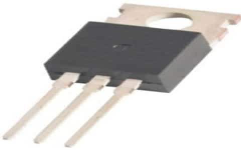
IRFZ44N MOSFET
It is most widely used to create motor controls for Arduino projects in H-bridge circuits. It has a high drain current of 49 Amps with low drain-to-source resistance of 17.5 mOhms and 4 Volts of the low threshold voltage. It needs a special driver circuit for complete and fast switching.
The conduction of IRFZ44N power MOSFET starts at a low 4V gate voltage and produces maximum drain current at 10V of gate voltage. To drive this MOSFET with a microcontroller or Arduino directly, IRFZ44N logic level type MOSFET is suggested.
Pin Configuration of IRFZ44N MOSFET:
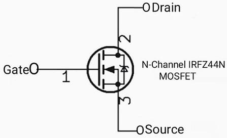
The IRFZ44N N-Channel MOSFET is available in 3-pin just like a general MOSFET. It is used as a general-purpose power MOSFET for various applications. The pin configuration of IRFZ44N N-channel power MOSFET is shown in the figure below.
IRFZ44N Pin Configuration
These power MOSFETs are available in a silicon-level design that adds a parasitic diode, which is a Zener diode (anti-parallel) across the source and drain terminals as shown in the figure, allowing the MOSFETs to operate in the reverse voltage. This diode acts as a protection diode.
- Gate: This terminal/pin is used for controlling the biasing of the IRFZ44N power MOSFET.
- Drain: This current into the IRFZ44N through the drain terminal.
- Source: The current flows out of the IRFZ44N via the source terminal
Features and Technical Specifications:
The following are the features and technical specifications of IRFZ44N MOSFET.
- It is a small signal N-channel Power MOSFET with a high drain current and fast switching speed available in the To-220 package.
- The maximum drain current (continuous) Id is 49mAmps.
- The peak pulse drain current is 160 Amps.
- The gate threshold voltage (VGS) (minimum) is 2V.
- The gate threshold voltage (maximum) is ±20V.
- Drain-to-Source voltage (VDS) is 55V maximum.
- The rise time is 60 nsec.
- Fall time is 45 nsec.
- Mostly interfaced with an Arduino because of the limited threshold current.
- Power dissipation is 94 Watts (maximum).
- The maximum storage and operating temperature range is -55°C to +175°C.
- Drain-to-Source resistance is 17.5 mohms.
- It has a fast switching capacity and advanced process technology.
- Ultra-low ON resistance and dynamic rating.
- The gate charge is low.
- RoHS compliant and lead-free.
- Pulse width is limited by maximum junction temperature.
Working of IRFZ44N:
The IRFZ44N N-Channel enhancement MOSFET is commonly referred to as a normally open switch and requires a voltage for conduction. As the gate voltage applied to the gate of IRFZ44N increases, then conduction increases. When a positive voltage is applied to the gate, electrons are attracted from the source and drain regions of the n-type channel, creating a channel for the electrons to reach.
The gate of the MOSFET is rapidly charged by the supply voltage. Even after the gate power is removed, the MOSFET remains in an ON state like a conventional capacitor Because the gate holds a charge until it discharges or a very small gate leakage current flows. To remove this charge, the gate must be removed.
This can be done by reconnecting the port to the original terminal. If enough stray charge builds up on the gate to raise the gate voltage above a threshold value, then IRFZ44N MOSFET can inadvertently fire, damaging the downstream circuit. Hence, whenever the gate voltage is removed, a pull-up/pull-up resistor usually appears between the gate and source, which removes the charge from the gate. In addition, it is recommended to install a pull-up Or pull-down resistor of 10K between the gates of the MOSFET.
Simple Switching Circuit Diagram using IRFZ44N and Protection Diode:
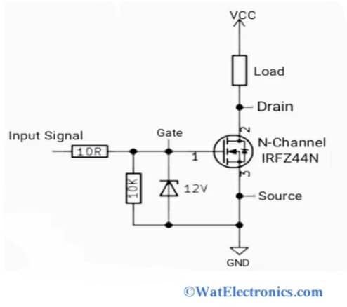
The basic and simple switching circuit diagram shown below explains the working of IRFZ44N N-channel MOSFET and protection diode. The implementation of this switching circuit is easy and simple and it works as a switching device. The load can be anything like car headlights and fan controllers. The source is connected to the GND (ground) pin and the drain pin is connected to the positive power rail.
Because the electrons are the negative charge carriers, which travel from the negative rail to the positive rail for this N-channel IRFZ44N MOSFET. As said, the IRFZ44N MOSFET is a voltage-controlled transistor, which means that the gate is conducting and needs a particular positive voltage to turn ON. The applied voltage at the gate generates an electric field that can increase the charge carriers’ count.
Simple Switching Circuit with Protection Diode
The absolute maximum gate-to-source voltage can be set to ±20V. Usually, the transistor starts to work only when the gate voltage is more than the source. MOSFETs have insulated gate junctions that represent capacitance. When voltage is applied at the gate terminal of the IRFZ44N, the electrical charge will be present at the gate junction for a longer time, maintaining the conduction of the transistor. To prevent this, a pull-up resistor is needed between the source pin and gate pin to dissipate the residual charge.
A Zener diode is used as a protection diode because the Gate of the IRFZ44N MOSFET is a very sensitive because of the thin oxide layer that insulates the gate from the channel. And also due to the Vgs=±20V.
Delay Timer Circuit using IRFZ44N:
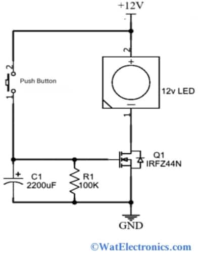
Sometimes you may notice that our electronic or electrical devices like refrigerators, washing machines, or other heavy equipment, take some time to turn ON. This is due to the delay timer protection circuit. This circuit protects the device from high voltages or sudden instabilities that could damage the device and the environment. The below delay timer circuit is built with IRFZ44N N-Channel power MOSFET as the main component. The switching characteristics of the delay timer circuit with rise time and fall time are shown in the figure below.
Delay Timer Circuit
Connect the circuit as shown in the above circuit diagram. When power is applied and the push button is pressed, current starts flowing from Vcc through the 220uF capacitor to the ground. So the capacitor is charged. When the switch is released, the capacitor begins to discharge through the gate terminal of the IRFZ44N, which makes turning/triggering, and current begins to flow from the source to the drain terminal. So, the load is energized. Here a 12V LED acts as a load. This application circuit is mainly used in the protection of electrical and electronic devices and power supply systems.
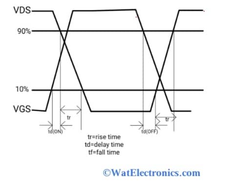
Switching Waveforms of Delay Timer Circuit
LED Dimmer/LED Flasher Circuit Using IRFZ44N:
Light, like intensity, plays a big role in everyone’s life. In this section is a small circuit shown called LED Dimmer using IRFZ44N MOSFET that helps to change and control The intensity of light. This circuit is very affordable and requires IRFZ44N, an N-type MOSFET chip, and a few components.
In the above circuit, the gate terminal IRFZ44N MOSFET is connected to a 250K potentiometer to change the gate voltage by rotation. Therefore the intensity/light of the LED strip depends on the rotation of the potentiometer. The source terminal of IRFZ44N is connected to one terminal of the LED. There is a common ground connection between the other end of the potentiometer and the LED strip. Power the circuit with a 12V positive power supply.
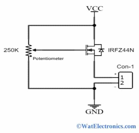
LED Dimmer Circuit
When the knob of the potentiometer is rotated, the gate voltage of the IRFZ44N changes. As the gate voltage increases, the intensity of the LED strip increases and works as a LED flasher. Similarly, with the decrease in gate voltage, the intensity of the LED strip decreases and works as a LED Dimmer circuit. This circuit is particularly used to change and control the light intensity of an LED and other lighting systems.
Interfacing IRFZ44N with Arduino UNO to Control Speed of the DC Motor / Arduino N-channel Power MOSFET
IRFZ44N MOSFETs are voltage-controlled transistors, which means that is turned ON or OFF with the application of certain or required gate threshold voltage (VGS). Because the IRFZ44N is an N-channel MOSFET, the channel and source pins remain open when the gate pins are not energized. When the voltage to the gate pin is applied, this pin closes. The Arduino IRFZ44N MOSFET is used to drive high-power circuits.
IRFZ44N MOSFETs are a type of transistor with an insulated gate terminal that makes it much safer and easier to use with an Arduino. If we want to activate the IRFZ44N MOSFET with Arduino, then a simple gate driver circuit with a particular gate voltage is necessary, that can trigger the MOSFET and open it completely.
The components required for interfacing IRFZ44N N-channel power MOSFET are,
- IRFZ44N.
- Arduino UNO.
- 12V Power Supply Or 9V battery.
- Breadboard.
- Connecting wires.
The interfacing diagram of IRFZ44N with Arduino to drive a high-power DC motor is shown below.
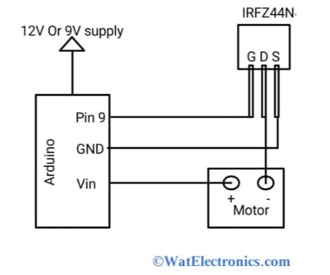
Interfacing IRFZ44N with DC Motor
The connections are made as per the above diagram. Connect PWM pin 9 of the Arduino to the Gate terminal of the IRFZ44N. Connect the Vin pin of the Arduino to one of the terminals of the motor.
Connect the GND pin of the Arduino to the drain terminal of the IRFZ44N. Connect the source terminal of the IRFZ44N to the other terminal of the motor. Power the whole circuit with a positive external supply of 12V or 9V. Use the analogue write function to monitor and control the speed of the DC motor with the PWM signal. When the relay is used, then the motor speed cannot be controlled with the PWM signal. Upload the Arduino code as shown below and observe the motor speed.
Arduino Code:
void setup() {
pinMode(9, OUTPUT);
}
void loop() {
for(int a = 0; a< 255; a++){
analogWrite(9, a);
delay(20);
}
for(int a = 255; a > 0; a–){
analogWrite(9, a);
delay(20);
}
}
As per the above code, the speed of the motor increases and decreases according to the delay. Monitor the speed with the obtained PWM signal.
If the gate pin of IRFZ44N with a 5V is connected directly to the Arduino’s I/O pin, then it will not open completely because the maximum drain current depends on the applied voltage at the gate pin. The transfer characteristics between gate-to-source (Vgs) voltage and drain-to-source voltage (Vds) shows the maximum drain current is obtained at a 4 V to 10V of a gate threshold voltage.
From the above figure, the IRFZ44N N-channel MOSFET is opened fully when the applied gate voltage is 10V. At 5V, the maximum drain current is 20 Amps.
Applications of the IRFZ44N
The following are the few applications of the IRFZ44N N-channel power MOSFET
- In switching of high power devices
- Controlling motor speed
- LED flashers and dimmers
- Converter and Inverter circuits
- Fast-speed switching applications
- Solar battery chargers and other applications
- Normal battery chargers
- Battery controlling and management systems
- Consumer applications
- Full bridge circuits
- Relay circuit applications
- Power supplies (uninterrupted)
- DC Motor driver circuits
Please refer to this for How to Select a Transistor.
Please refer to this link for IRFZ44N Datasheet , MX1508 DC Motor Driver Datasheet.
Thus, this is all about an overview of the IRFZ44N N-channel power MOSFET. The alternatives of this IRF series power MOSFET are IRF2807, IRFB4710, IRFB3207, IRF540N, IRF640N, IRF44N, IRF740N, IRF3205, IRF9540, IRF840, and IRF740. The main drawback of IRFZ44N MOSFET over IRLZ44N MOSFET is, it requires the gate driver circuit with a microcontroller or Arduino to turn ON completely. Since it turns ON partially and produces a limited drain current with a 5V of the gate threshold voltage. Here is a question for you, what is MOSFET?