In automobiles, there are various sensors to control all engine functions and work to indicate failures and protect the vehicles from damage. Air Flow Sensor or Mass Air Flow (MAF) sensor is one detection device, which can convert the amount of air entering the vehicle’s engine into a voltage signal to calculate the load of the engine. This sensor is necessary to determine the amount of fuel injection, when to fire the cylinders, shifting of gears, and calculate the exact air-fuel ratio/flow rate. This article gives a brief description of the working of an airflow sensor or mass air flow sensor.
What is an Air Flow Sensor?
The Mass Air Flow Sensor is simply called a MAF Sensor or air flow sensor, or air meter. Despite the many names, the main task is to measure the amount of air entering the engine. The PCM/ECM then utilizes data information to monitor and calculate the exact amount of fuel required for the optimum air-fuel ratio. If this information is inappropriate or without this information, the ECU can’t control fuel injection accurately, and the engine will not run.
Because the number of other parts like wires, bad/faulty spark plugs, injectors, etc. can reflect these symptoms, a MAF sensor fault can be difficult to diagnose. But with expert advice from the user can know how to replace a failed device if it breaks. The airflow sensor in vehicles is shown below.
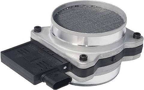
Air Flow Sensor Diagram
Air Flow Sensor Working Principle
The air mass sensor is located directly in the intake air stream between the air filter and the throttle body to measure the intake air. The airflow sensor working principle is explained from the block diagram as shown below.

Air Flow Sensor Block Diagram
Most of the airflow sensors are mounted on the intake manifold/pipe between the air filter housing and the intake manifold and work on the hot wire technique which means measuring the amount of current flowing to the resistive or hot wire and the amount of current needed to keep it warm.
The airflow sensor has two sensor wires- one is electrically heated, and the other is not. It cools down as air passes through the heating wire. When the difference in temperature between the 2 sensor wires changes, the airflow sensor will automatically increase or decrease the current flowing through the hot wire to compensate. The current is then sent to the ECU and converted to voltage Or frequency which is translated as airflow. The amount of air entering the engine is adjustable.
Air Flow Sensor Circuit Diagram
The basic air flow sensor circuit diagram shown below explains its working using hot-wire method. The main components of an airflow sensor using hot-wire are a platinum heating wire, a thermistor, and an electronic control circuit.
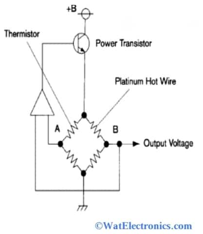
Air Flow Sensor Circuit Diagram
Thermistors measure the incoming air temperature. An electronic control circuit connected to the thermistor helps to maintain a constant temperature in the heating wire (hot wire). As airflow increases, heat dissipates faster from the heating wire, and the electronic control circuit or ECM compensates by passing more current through the hot wire. The electronic control circuit/ECM measures the flowing current simultaneously and outputs a voltage signal proportional to the flowing current.
Air Flow Sensor Wiring Diagram
The mass air flow sensor or air flow sensor wiring diagram is designed by the manufacturer according to the year, model, construction, type, and demand. There are 4 forms of air flow sensor wiring diagrams. They are,
- 3-wire mass air flow sensor wiring diagram (hot wire-reference voltage from ECU, ground wire, signal wire).
- 4-pin/4-pin mass air flow sensor wiring diagram (positive power supply 12V, MAF ground, IAT signal, MAF signal).
- 5-wire mass air flow sensor wiring diagram. (MAF ground, MAF signal, MAF power, air temperature signal, air temperature reference voltage).
The 4-wire air flow sensor wiring diagram is shown below and explained in this section.
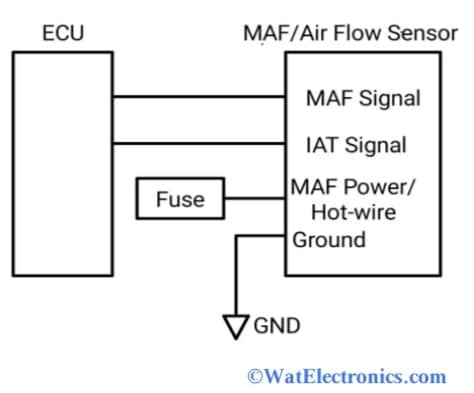
Air f low Sensor Wiring Diagram
There are 4 wires in this wiring diagram, which are 12V positive power supply, MAF ground, IAT (Intake Air temperature signal) signal, and MAF signal.
A positive power supply of 12V or called hot-wire is connected to a relay and a fuse in the fuse box. The mass air flow signal wire is connected to the vehicle’s ECU. This wire transfers the signal of the sensor (output voltage) to the ECU. MAF ground wire is used as a common ground connection for both vehicle’s ECU and sensor.
The airflow sensor signal circuit is built into the mass air flow sensor to calculate the amount of current flowing through the sensor, convert this current into voltage, and transmit it to the vehicle’s ECU via the air flow sensor or MAF signal cable. This signal circuit is separately grounded. In addition, the airflow sensor has an integrated IAT sensor, which gives the IAT signal to detect the intake air temperature signal.
Air Flow Sensor Types
Air flow sensors are used to determine the mass or volume of flow of air in a channel. There are 2 categories of airflow sensors. They are volume air flow sensors and mass air flow sensors (MAF). These categories are further divided into different types, which are explained below.
Volume Air Flow Sensors
It is a type of airflow sensor is called the Karman Vortex airflow sensor. These are used to detect airflow using optical sensors that monitor the frequency of artificial turbulence. Then the ECM calculates the volume of flow of air by combining the information of volume air flow air temperature measurements. The volume air flow sensor is shown below.
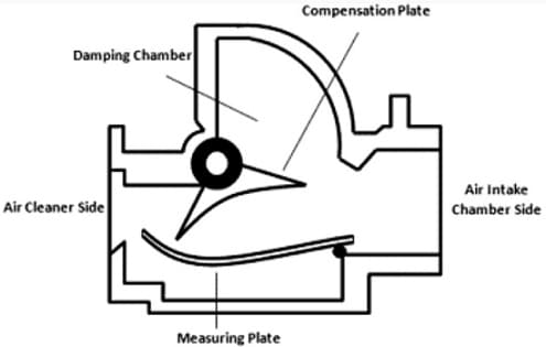
Volume Type
Mass Air Flow Sensors
This type of sensor is most widely used in automobiles to detect the mass of flow of air that enters the vehicle’s engine and the amount of fuel injection. The MAF sensor is shown below. These sensors are further divided into 3 types. They are;
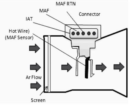
Mass Air Flow Type Sensor
Vane Type Mass Air Flow Sensor (MAF)
This type of MAF is used to monitor and measure the amount of air flowing via a vehicle’s engine air intake by placing a vane in the air stream.
Hot-Wire Mass Air Flow Sensor
This type of MAF is used to measure the rate of flow of air by placing the thin resistive (hot) wire down to the airflow. The hot wire is heated at a temperature of 100°F above the ambient temp that is detected by the IAT (intake air temp) sensor.
Cold-Wire Mass Airflow Sensor
This type of MAF measures the airflow by detecting the varying inductance of thin metallic strips of a circuit, which vibrates when air passes.
MEMS Devices
This type is used to detect the rate of airflow by observing the temperature changes of a membrane (heated). It is similar to the hot-wire MAF.
Air Flow Sensor Interfacing with Microcontroller
The airflow sensor or anemometer is an inexpensive airflow sensor that is suitable for interfacing with Arduino. This sensor is also referred to as Wind Sensor, it has hardware ambient temperature compensation and stands for PTC (positive temperature coefficient) thermistor. This sensor is used to detect cyclones without saturation. It detects wind speeds from 0-150 mph and provides up to 3.3V measurement output voltage, Therefore it is ideal for a variety of Arduino microcontrollers and development boards.
This wind sensor uses a thermal anemometer or hot wire technology to detect/sense through the heating element/hot wire and measure the difference in power required to keep the heating element warm during air/wind flow. When the flow of air increases, the heating element suddenly loses heat and requires more energy/power to keep warm, and the heating element remains stable when there is no wind. So it measures and draws the difference between the current and power flowing through the heating element.
Pin Description of Wind Sensor:
The airflow sensor or wind sensor in Rev. P version (wind sensor Rev.P) comes with 5-pins with hardware compensation for ambient temperature, which is shown in the below figure.
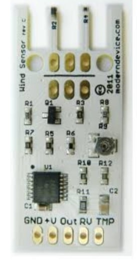
Wind sensor Rev.C
GND: This pin refers to the ground pin, which is used for common ground connection for the circuit.
V+ (4-5V or 4-10V): This pin refers to the input voltage of the sensor, which is a positive power supply of 10-12V connected to the Arduino.
OUT/Ao: This pin to the analogue output signal of the sensor. It is used to determine the amount of current flowing through the sensor
TMP: This pin gives the temperature output. It is a simple voltage divider with a thermistor and resistor. It reads 2.8V at room temperature. The output of this pin is high at low temperatures and goes down at high temperatures.
RV: This is the reference voltage and the output voltage, used for the calibrated output. It does not drop below 1.8 volts even at room temperature. The calibration potentiometer does not affect this voltage.
The technical specifications are given below,
- Voltage Supply: 4-5V.
- Supply Current: 20-40mA.
- Wind Velocity: 0-60mph.
The airflow sensor or wind sensor interfacing with an Arduino microcontroller is shown in the figure below. The components required are,
- Arduino UNO
- Wind sensor Rev. P Or wind sensor Rev. C
- Power supply 9V Or above
- Connecting wires.
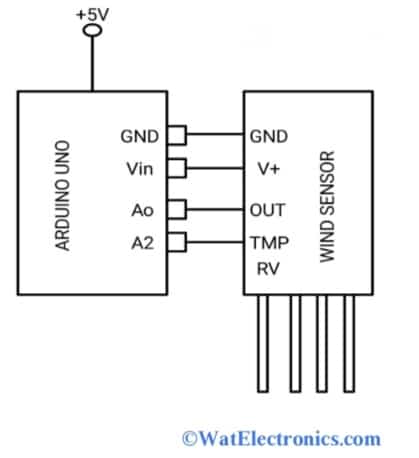
Air Flow Sensor Wind Sensor Interfacing Circuit
Make the connections as shown in the above interfacing circuit. Connect the sensor’s GND pin to the Arduino GND pin; the sensor’s V+ pin to the Arduino Vin pin; the sensor OUT pins to the Arduino Ao pin (analog pin); sensor’s TMP pin to the Arduino A2 pin. The RV pin of the sensor is not connected.
Power up the Arduino board with 9V Or above by using an external power board and power the wind sensor from the Vin pin of the Arduino board. Upload the air flow sensor Arduino code as shown below and monitor the analogue output voltage and temperature changes on the OUT pin and TMP pin of the sensor to detect the speed of the wind. The output of the sensor is logarithmic. This means that the sensor can pick up and monitor very little airflow at low levels, but it won’t saturate at full power until the airflow reaches about 60mph.
This voltage signal obtained from the Ao pin of the sensor is directly proportional to the speed of the wind. The basic principle of the sensor works in the same way as conventional hot wire technology. This method is excellent for low to moderate wind speeds and this method is applicable for measuring indoor airflow direction.
Advantages
The following are the advantages of the airflow sensor.
- More design options are available.
- Cost-effective.
- Faster response to changes in the flow rate of air.
- Less sensitive to orientation and location.
- Durable because of no movable parts.
- No use of temperature and pressure sensors.
- Small size.
- Installation is easy.
- Measures static pressure, average air velocity, and total pressure.
Disadvantages
The following are the disadvantages of airflow sensors Or flow sensors Or mass flow sensor
- Poor stability.
- They are not used to measure low-density liquids.
- High sensitive
- Affected by Vibration interference.
- Contaminated quickly due to oil and dust, which leads to failure and malfunctioning of the sensor.
- Accuracy is less due to contamination.
- Calibration is necessary to analyze the mass or airflow.
- Reduced air intake affects the performance of the sensor.
- Conductivity is low 0.05 micro sec/cm.
- Errors due to gas inclusions.
Air Flow Sensor Applications
The airflow sensor applications are listed below.
- Used to measure and control of flow rate of air in ventilation and ACs.
- Used to analyze the flow rate of mass Or air in fuel-injected combustion engines.
- Industrial, commercial and automotive applications.
- Medical devices.
- Analytical applications.
- Testing applications.
- Chemical factories etc.
What are the symptoms of a bad mass air flow sensor?
The symptoms or signs of bad mass air flow sensor are black exhaust, hard starts, hesitation (fuel and air imbalance), check engine light ON, poor gas economy rough idle, trouble accelerating, faults in electrical connections, mechanical damages due to vibrations, and low compression.
What is the purpose of the airflow sensor?
The purpose of an airflow sensor Or mass flow sensor is to detect the mass flow of air entering a fuel-injected internal combustion engine. Because the information about air mass information is required by the engine control unit (ECU) to balance and deliver the correct fuel mass to the engine.
What is a flow rate sensor?
An electronic device that can regulate or measure the flow rate of gases and liquids in tubes and pipes to display measurements is called a flow rate sensor Or flow meter Or flow sensor. They can be connected to a computer and digital interfaces.
Where is the airflow sensor used?
Air flow sensors are used to determine the mass or volume of air passing through a channel. For example in automobiles, these are used to find the amount of air entering the engine through the intake manifold.
What type of sensor is commonly used for air flow measurement in vehicles?
Thermal anemometer principle-based sensors are used to measure the mass flow rate of air entering an engine in vehicles. They are hot wire anemometers, and hot film anemometers (also used in applications of exhaust gas).
Thus, this is all about an overview of airflow sensors working. The advanced low voltage thermopile-based air velocity measuring modules with both analog and digital output are FS1015, FS3000, FS1012, FS2012, MFS-02, wind sensor Rev. P, etc. The basic air flow sensor designs are available in both digital and analog to determine frequency output and variable voltage output.