Measuring current within any system without affecting its performance is significant. So, current measurement is very essential in many instrumentation and power systems. Usually, current sensing was mainly for protection & control of the circuit. But, with the progress in technology, sensing current has appeared as a technique to examine and improve performance. So knowing the sum of current being transmitted to the load is very helpful for an extensive variety of applications. So this article discusses an overview of a current sensor – working with applications.
What is a Current Sensor?
A device that is used to detect & also change current to assessable output voltage is known as a current sensor. This output voltage is simply proportional to the current flow throughout the measured path. After that, this output voltage signal is used to display the current measured within an ammeter, for controlling purposes or simply stored for more analysis within a data acquisition system. So this is the function of a current sensor.
There are different types of sensors available in the market and each sensor is used for a particular range of current & ecological conditions. As compared to all these sensors, a current sensor is most frequently used by considering it as a current-to-voltage converter by placing a resistor into the flow of the current path, so the current is changed into voltage in a linear mode. The technology utilized by this sensor is significant because different kinds of sensors can contain different characteristics for various applications.
Current Sensor Working Principle
The working principle of the current sensor is; once current is supplied throughout a circuit or a wire then a voltage drop takes place and also magnetic field will be generated nearby the current-carrying conductor. So, there are two kinds of current sensing direct current sensing & indirect current sensing.
Direct sensing mainly depends on Ohm’s law whereas indirect sensing depends on Ampere’s & Faraday’s law. Direct Sensing is used to measure the voltage drop associated with the flow of current throughout passive electrical components. Similarly, indirect sensing is used to measure the magnetic field nearby a current-carrying conductor. After that, the magnetic field which is produced is used for inducing proportional current o voltage which is afterward changed to use measurement or control purposes.
Current Sensor Specifications
The current sensor specifications mainly describe how the sensor operates and interacts in the preferred environment. So, the specifications of this sensor are discussed below.
Measuring Range
The measuring range is the highest flow of current that a current sensor can measure up to 120A.
Input Voltage
This is the required voltage to activate the device is +5V.
Frequency Range
The range of frequency this sensor can operate is 20Hz – 20kHz.
Response Time
The response time of this sensor is the time taken between the input excitation application & the appearance of the equivalent o/p signal. The response time of this sensor is < 20 ns.
Isolation Voltage
The isolation voltage is the voltage that a sensor can handle to defend the devices connected to it. If the voltage range is increased than the fixed range then it can damage the current sensor & gives inaccurate measurements.
Accuracy
The accuracy of the current sensor is above 90%.
Types of Current Sensor
Current sensors are designed in different types like wireless, analog, and digital. These are used as sensing devices based on the type of benefit. These sensors will monitor the current values continuously in the appliances or machines within various applications.
Shunt Resistor
Shunt resistor type current sensor is mainly used for measuring DC current. Once a DC current is supplied throughout a resistor, then the voltage will be produced across the resistor, so the shunt resistor is designed based on this principle. The main benefits of these sensors are less cost, response speed is fast, and accuracy is high whereas the drawbacks are; the measurement circuit is not isolated electrically from the flow of the current being measured. This is appropriate in small amplitude and low-frequency current measurements.
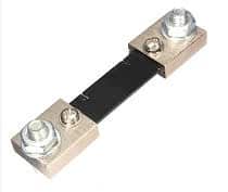
Shunt Resistor
Hall Effect Current Sensors
Hall current sensor is made according to the Hall effect and Ampere’s law principles. These sensors are used for measuring both AC & DC currents with up to 100 KHz frequency. These sensors mainly include a Hall effect device, core, and signal conditioning circuitry. They operate based on the Hall Effect which states that, once current is supplied throughout a conductor then it forms a magnetic field.
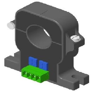
Hall Effect Current Sensor
If this conductor is arranged in another magnetic field, then the magnetic field generated by the conductor will communicate with the external magnetic field so that electrons move to a single side of the conductor. So, this will create a voltage that is proportional to the flow of current throughout it & can be measured. The main benefits of these sensors are good isolation & high precision whereas their drawbacks are; the influence speed is very slow. It has high precision and good isolation and the disadvantages are; the influence speed is slow & small current measurement lacks accuracy.
Current Transformer
A current transformer is also known as a current sensor which works based on the electromagnetic induction principle. The main function of this is to change the main large current value into a second smaller current value for measurement & protection purposes.
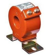
Current Transformer
A current transformer mainly includes a closed iron core as well as windings. The primary winding of this includes less number of turns & is simply connected in series within the current line to be measured; consequently, it frequently has the flow of current through it whereas the secondary winding includes more turns & is simply connected in series within the measuring instrument as well as the protection circuit. Once this transformer starts working, then its secondary circuit is closed always, thus the series coil impedance for the protection circuit & measuring instrument is extremely small.
Flux Gate Current Sensor
The structure of the flux gate current sensor is the same as a current sensor including a magnetic balance system, apart from that it includes a magnetic probe coil in place of a Hall element. This sensor detects the current which ranges from 6 – 600A & it is ideal for most medical & industrial equipment that need high-accuracy measurement. The characteristics of this sensor are reliability, high resolution, a wide range of weak magnetic field measurements, and the magnetic field’s component direct measurement, These sensors are appropriate in high-speed motion systems.
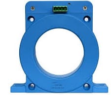
Flux Gate Current Sensor
Current Sensor Circuit Diagram
The current sensor switch circuit diagram is shown below. Generally, current sensors are mainly used where there is a necessity for the measurement of the amount of current used by a particular device or appliance. There are different techniques are available to measure the flow of current. So in this circuit, we are using a Hall effect current sensor like ACS712 IC.
ACS712 IC Pin Configuration
The ACS712 IC includes 8-pins where each pin and its function is discussed below.
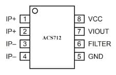
ACS712 IC Pin Configuration
- Pins 1 & 2 (IP+): These are positive terminals that are used for sensing current.
- Pins 3 & 4 (IP-): These are negative terminals that are used for sensing current.
- Pin5 (GND): This is a Ground pin.
- Pin6 (FILTER): This pin is used for the external capacitor that sets the bandwidth.
- Pin7 (VIOUT): This is an analog output signal pin.
- Pin8 (VCC): This is a power supply pin.
The IC ACS712 is a low-cost Hall Effect current sensor used to measure up to 20A current. This IC includes a copper conduction lane through which the flow of current is measured. The o/p voltage of this is proportional to the input flow of the current.
Working
The working of this current sensor circuit is quite simple. Once current is supplied from Pins 1,2 and 3,4 throughout the conduction lane, then it produces a magnetic field which is detected by the hall effect sensor. After that, it is changed into proportional o/p voltage. So, this equivalent o/p voltage will be attained from the pin-1 of the ACS712 IC.
The o/p from this circuit is used with Microcontroller’s Analog pins & thus accurate current flow value can be simply determined. So, this kind of current sensor module is used in Microcontroller based applications.
Current Sensor Arduino
The current sensor interfacing with a microcontroller like Arduino Uno is shown below. This interfacing provides how to connect an ACS712 current sensor with an Arduino board to measure current. Generally, a current sensor is an essential device used in management and power calculation-based applications. This interfacing helps in measuring the flow of current in a circuit or a device & generates a suitable signal that is simply proportional to the measured current. Generally, the o/p signal is an analog voltage.
The ACS712 Current Sensor in this interfacing is used to measure both AC & DC currents precisely. So this current sensor is based on Hall Effect & this IC includes an inbuilt Hall Effect device. The output of this sensor is an analog voltage that is proportional to AC/DC currents
The required components to build this circuit mainly includes a power supply, load, ACS712 current sensor, Arduino Uno board, LCD, 10-kilo ohm Potentiometer, 330 ohms resistor, and connecting wires.
Here, a 12V DC Motor is used as a load with a 12V power supply. The ASC712 current sensor module board’s screw terminals are simply connected with the power supply & the motor in series as shown in the following diagram.
After that, connect the VCC of the sensor to the 5V pin of Arduino, the GND pin of the sensor to the GND pin of Arduino & OUT pin of the sensor to the A0 pin of an Arduino board. The RS, E, and D4 to D7 pins of 16×2 LCD are connected to Arduino’s Digital I/O Pins7 to 2. Finally, the result is displayed on a 16×2 LCD. A 10KΩ POT is simply connected to LCD’s Pin-3 & its VCC & GND pins are simply connected to +5V & GND.
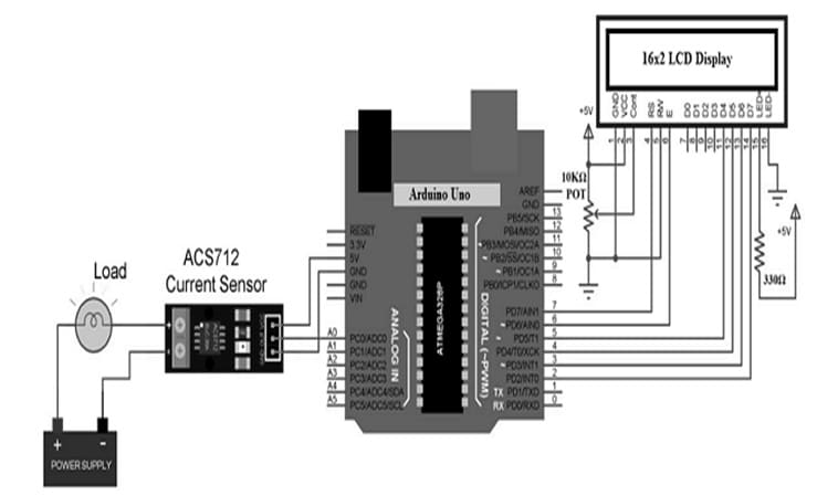
ACS712 IC with Arduino Uno
Arduino Code
#include <LiquidCrystal.h>
LiquidCrystal lcd(7, 6, 5, 4, 3, 2);
const int currentPin = A0;
int sensitivity = 66;
int adcValue= 0;
int offsetVoltage = 2500;
double adcVoltage = 0;
double currentValue = 0;
void setup()
{
Serial.begin(9600);
lcd.begin(16, 2);
lcd.print(” Current Sensor “);
lcd.setCursor(0,1);
lcd.print(” with Arduino “);
delay(2000);
}
void loop()
{
adcValue = analogRead(currentPin);
adcVoltage = (adcValue / 1024.0) * 5000;
currentValue = ((adcVoltage – offsetVoltage) / sensitivity);
Serial.print(“Raw Sensor Value = ” );
Serial.print(adcValue);
lcd.clear();
delay(1000);
//lcd.display();
lcd.setCursor(0,0);
lcd.print(“ADC Value = “);
lcd.setCursor(12,0);
lcd.print(adcValue);
delay(2000);
Serial.print(“\t Voltage(mV) = “);
Serial.print(adcVoltage,3);
lcd.setCursor(0,0);
lcd.print(“V in mV = “);
lcd.setCursor(10,0);
lcd.print(adcVoltage,1);
delay(2000);
Serial.print(“\t Current = “);
Serial.println(currentValue,3);
lcd.setCursor(0,0);
lcd.print(“Current = “);
lcd.setCursor(10,0);
lcd.print(currentValue,2);
lcd.setCursor(14,0);
lcd.print(“A”);
delay(2500);
}
Working
Once the connections are made, the above code needs to be uploaded into the Arduino board. So in this code, there is a minute calculation to measure the current. Initially, assuming the power supply (VCC) to the current sensor is 5V. When there is no flow of current throughout the IP+ & IP- terminals, then o/p voltage from Vout of ACS712 is 2.5V. So this means, we have to deduct 2.5V from the measured voltage at the analog pin.
So as to calculate the current value, need to divide this value by the sensitivity of the current sensor like 185mV/A is for 5A Sensor, 100mV/A is for 20A Sensor & 66 mV/A is for 30A Sensor. So, this circuit is used in various current measuring applications such as; SMPS, Inverters, chargers of battery & automotive applications like Power Steering, Inverters, etc.
Testing of Current Sensor
The current sensor testing is essential to check whether they are providing accurate readings. If the sensor readings are correct, then these sensors are used for monitoring the flow of current to the motor. We can able to change the chassis if a specific motor is getting too much or little current. This test is used to check the earlier generations of current sensors. Because of the previous short-circuiting, these sensors need to be tested to observe if they are operational. These sensors must work properly to measure & evaluate devices.
Advantages & Disadvantages
The advantages of the current sensor include the following.
- The generation of heat is low due to the low resistance of the primary conductor.
- It simply supports a broad measurement range of current which ranges from ±5 to ±180A.
- The bandwidth can be extended.
- High resolution can be attained.
- It is feasible to attain high accuracy & low offset.
The disadvantages of the current sensor include the following.
- The generation of heat and the value of resistance are higher.
- Large current measuring is difficult.
- The hall element sensitivity is low.
- This sensor is not applicable for discovering the location of non-conductive materials.
- These are extremely temperature sensitive.
Current Sensor Applications
The applications of the current sensor include the following.
- Current sensors are used to measure the flow of electric current and based on their usage, these are available from sensors that measure few mA current to high thousand Ampere current.
- These sensors are also called magnetic sensors which can be used in smart grids, household appliances, wind power generation, electric vehicles, etc.
- These sensors are also used in household appliances compasses, computer hard drives, etc.
- These are sensing devices mainly used to measure the changes within particular parameters & also the current values of the commercial components & particular appliances.
- Current sensors are very useful in power metering, measurement of current supply, diagnosis of the control system, controlling loads from motors, etc.
- These sensors are used in charge integration & rechargeable batteries condition monitoring.
- These are applicable from facility management to sub-metering & many more.
- These sensors help in detecting faults within machinery to avoid equipment damage.
- Specialized current sensors are used in commercial appliances which frequently include security cut-off features & surge trips.
Thus, this is all bout an overview of a current sensor – interfacing, types & its applications. This is one kind of detection device used to measure the measured current data & this data can be changed into electrical signals. Here is a question for you, what is an alternate name for a current sensor?