In digital electronics, logic gates are the basic building blocks. Every logic gate implements an exclusive Boolean function whereas a complex Boolean expression can be implemented with the network of logic gates. Three basic digital logic gates are AND, OR & NOT where these logic gates are connected to make other significant logic gates like NAND gate, XOR gate, NOR gate & XNOR gate. So among all logic gates, OR gate is one kind of digital logic gate mainly designed and used for arithmetic & logical operations. So this logic gate is applicable wherever mathematical calculations are required. This article discusses an overview of the 74LS32 OR gate which is also known as the 74LS32 quad-2-input OR gate.
What is 74LS32 Quad-2-Input OR Gate?
The 74LS32 IC is a quad dual input OR logic gate which means it includes four separate OR logic gates where each gate performs the function of logic OR. As the name suggests, each gate in this IC has two inputs. This 74LS32 IC working voltage range is wide and it can be interfaced directly with TT, CMOS & NMOS. The output of the Quad-2-Input OR gate comes in TTL always which makes it simple to work through other TTL devices as well as microcontrollers. This IC is available in small size & it has faster speed.
Pin Configuration:
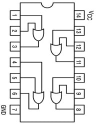
The pin configuration of the 74LS32 quad-2-input OR gate is shown below. This OR gate IC includes 14 pins and each pin and its functionality is discussed below.

74LS32 OR Gate IC Pin Configuration
- Pins 1,4,9 &12 (Input pin (A)): These are the first input pins of OR gates.
- Pins 2,5,10 & 13 (Input pin (B)): These are the second input pins of OR gates.
- Pins 3,6,8 & 11 (Output pin (Q)): These are the output pins of OR gates.
- Pin7 (Ground): It is a ground pin of the IC.
- Pin14 (Vcc)): It is the power pin of the IC typically +5Volts.
Features & Specifications:
The features and specifications of 74LS32 quad-2-input or gate are discussed below.
- It is a quad package 2-input OR gate.
- It is manufactured by Texas Instruments
- Its voltage supply ranges from 5 to 7V.
- Its input voltage ranges from 5V to 7V.
- Its operating temperature ranges from -55°C – 125°C.
- The available package is 14-pin SOIC.
- Its series is 74LS,
- The type of packaging is Tube
- The logic type is OR gate.
- The type of mounting is through the hole.
- The low logic level is 0.8V.
- The high logic level is 2V.
Equivalent & Other Logic Gates
The equivalent 74LS32 logic gate is CD4071 whereas other logic gates are; 74LS08, 74LS00, 74LS02, 74HCT04 & 74LS04.
74LS32 OR Gate Working
74LS32 OR Gate includes 8 input and 4 output pins because it includes 4 OR gates within the IC. This IC can be used just by powering it with the Vcc & GND pins. So, this IC works with a +5V operating voltage. The o/p voltage of this OR gate IC is equivalent to the operating voltage. According to the truth table of the OR logic gate, whenever either one input or two inputs of the logic gate is HIGH then the output will be HIGH and when two inputs are low then the output will be low. The OR gate truth table is shown below.
|
A |
B |
Y |
|
0 |
0 | 0 |
|
0 |
1 | 1 |
| 1 | 0 |
1 |
| 1 | 1 |
1 |
74LS32 Quad-2-Input OR Gate Circuit
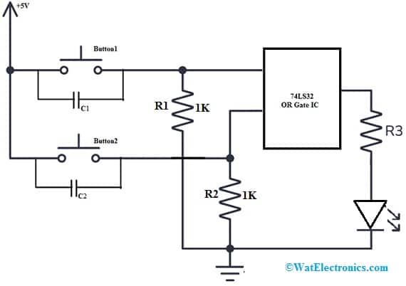
The 74LS32 Quad-2-Input OR logic Gate IC includes four OR logic gates and this IC is mainly designed to use where there is a requirement for mathematical calculations like arithmetic & logic. These logic gates have limits for input logic frequency & working voltage. Once these limits are not considered then this IC may get damaged. The 74LS32 quad-2-Input OR gate circuit diagram is shown below.
The required components to make this gate circuit mainly include; 74LS32 Quad OR Gate IC, 5V power supply, 1K resistors-2, 220Ω resistor, LED, 2 buttons, 100nF capacitors -2, breadboard, and connecting wires. Connect the circuit as per the circuit shown below.

74LS32 OR Gate Circuit Diagram
Working
In the above 74LS32 Quad-2-Input OR gate circuit, both the inputs of the logic gate are pulled down with a 1KΩ resistor. After that, the two inputs are connected to the power supply through a button. Once the button in the circuit is pushed then the equivalent gate input pin goes high. So by using two buttons in the circuit, we can understand the OR gate truth table.
Once one of the buttons in the circuit is pushed then one input of the logic gate will be HIGH & the other input will be LOW then the output will be HIGH. Once both buttons are pushed, then both inputs of OR logic gate will be HIGH, then the OUTPUT of this gate will also be HIGH.
Once both buttons in the circuit are released, both OR gate inputs will be LOW, then the o/p of this gate will be LOW. So according to the OR gate truth table above, the LED must be OFF simply whenever both buttons in the circuit are released.
Please refer to this link for OR Gate Advancements.
Advantages
The advantages of 74LS32 quad-2-Input OR gate include the following.
- The 74LS32 IC can be interfaced with CMOS, NMOS, & TTL directly.
- These OR gates are versatile, so utilized in a broad range of digital circuits.
- These are reliable, so they can resist harsh environments.
- These logic gates are relatively low-cost.
- These ICs are simple to use.
- These logic gates can be implemented in different ways.
- This IC is available in small sizes,
- It has a very fast speed.
Applications
The applications of 74LS32 quad-2-Input OR gate include the following.
- These ICs are utilized in basic logic circuits to merge two or above signals.
- It is used within data validation circuits to make sure that the input data is applicable.
- This IC is used to interface two circuits through different logic levels like between digital logic & TTL logic.
- These logic gates are fairly common within memory circuits for storing data in a non-volatile way.
- It is used within sequential circuits for controlling the timing of the event.
- These ICs are utilized in process control systems for controlling the signal flow.
- These are used in digital signal processing for combining several signals.
- It is used in computer networking to allow communication between two PCs.
- These are used in encoders, decoders, multiplexers, de-multiplexers, oscillator circuits, networking & digital systems.
- These ICs are used within stepper motors used in industries.
- These are used in automatic digital control circuits, doorbell switches, notebooks & PCs.
Please refer to this link for 74LS32 Quad-2-input OR Gate Datasheet.
Thus, this is an overview of the 74LS32 quad-2-input OR gate, pinout, features, specifications, and its applications. This IC is a 14-Pin Quad 2-Input OR Gate IC that includes two independent input OR gates by typical push-pull outputs. This IC operates with a power supply that ranges from 2.0V – 6.0V. Here is a question for you, what are AND gate ICs?