Relay is an electromechanical switch that uses low-power signals for controlling high-power loads by providing electrical isolation between the control circuit (CU) & the electrical load. These devices are frequently used for controlling electric motors, lights & high-power devices. These can be controlled by different signals of sensors, microcontrollers, or switches. Relays play a key role in switching different types of loads separately & also protect sensitive electronic components from high currents & voltages. Similarly, a relay module is a simple circuit board that includes a minimum of one or above relays & other components for providing isolation as well as protection. These modules are available in different sizes and shapes with two, four, or eight relays mounted above them. So these modules are very popular to switch power systems. This article discusses an overview of a 5V single-channel relay module, its working & its applications.
What is 5V Single Channel Relay Module?
A single-channel relay module that works with 5V DC is known as a 5V single-channel relay module. The input voltage of this module is taken from any logic chip or microcontroller that gives a digital signal as an output. This module is an electromagnetic switch that is operated electrically to control a circuit by turning it ON/OFF.
The relay module includes two parts; the relay & the control module. The relay mainly includes the coil, armature & contacts. The coil is used to create the magnetic field, the armature moves to attach or separate an electrical circuit & contacts are used to open & close to activate the load switch.
The relay control module includes the input and output terminals. The input terminals are used for connecting to the microcontroller whereas the output terminals are used for connecting the load. The control module includes LED indicators & other devices like transistors, protection diodes, resistors & other semiconductor devices which are required for its function.
Pin Configuration:
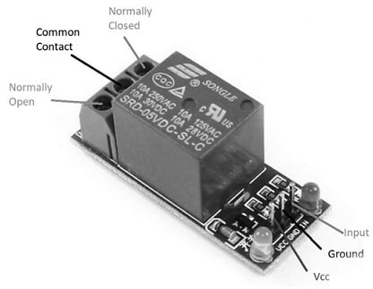
The pin configuration of the 5V single-channel relay module is shown below. The 5V relay module includes pins on the input side & output side where the input side gets the trigger signal & the output side control the connected load.

Relay Module Pin Configuration
The input side of this module includes 3 or 4 pins which are explained below.
- VCC Pin: This is the power connection pin of the relay module, used to supply 5V DC. This pin is connected to the positive terminal of the power supply.
- GND Pin: This is the GND connection pin that is connected to the negative terminal of the power supply.
- IN1 & IN2: These are the two input pins wherever the trigger signal is given. IN1 is the input pin of a single-channel module whereas IN2 is the input pin of the dual-channel module. The IN pin is simply connected to the o/p of the sensor, logic device, or microcontroller.
The output of this relay module includes three connections which are discussed below.
- Normally Open (NO): This pin is the connection of load whenever the relay is turned ON. Once the relay is turned off, then this pin maintains an open connection through the COM.
- Common (COM): The COM pin of the relay module is the common connection for both the normally open (NO) & normally closed (NC) pins.
- Normally Closed (NC): The NC pin is the load connection pin that connects to the common connection terminal when the relay is turned OFF or by default.
Features & Its Specifications:
The features and specifications of the 5V single-channel relay module are discussed below.
- It is a single-channel relay module.
- This module has two contacts NC and NO.
- It has a high-impedance controller pin.
- It has a power supply indicator LED.
- It has a high-level trigger by default.
- It has a pull-down circuit for avoiding malfunction.
- It controls various appliances through a large current.
- It is controlled by the standard TTL logic level.
- This relay module is compliant with international security standards.
- It has four fixed 3.1mm diameter screw holes.
- Its voltage supply ranges from 3.75V – 6V
- Its quiescent current is 2mAmps.
- The current required to activate the relay is 70mAmps.
- Its max contact voltage is 250VAC/30VDC.
- Its maximum current is 10 amps.
- Its max load current is 10A/30V DC, 10A/250V AC.
- Its max switch voltage is 250V AC, 30V DC
- Its operating time is ≤ 10ms.
- Its release time is ≤ 5ms.
Components
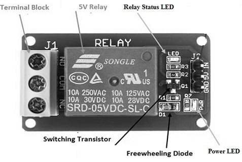
The 5V single-channel relay module includes different components like a relay, status LED, an output terminal, power LED, freewheeling diode, switching transistor, and input connector which are discussed below.

Components of Module
The 5V relay in this module is a blue color plastic and it has a max operating voltage & current for both AC & DC load mentioned on it. The part number SRD-05VDC-SL-C shows the operating voltage. A 5Volts active low or high signal triggers the relay by strengthening its coil.
The output terminal of this module is available on the left side which is mainly used for connecting an AC/DC load & input power source.
The status LED in this relay module is connected with the help of a current-limiting resistor in the top right corner. This LED is used to specify the condition of the 5V relay. When the relay is ON, the LED turns on.
The power LED in this module is used to show the condition of the connected power source through this relay module. Do not provide above 5Volts to Vcc & GND pins of the relay module, because high voltage may harm both the power & status LEDs.
A freewheeling diode (flyback diode) in this module is simply connected across the coil for avoiding the back EMF effect because the coil used within this relay is an inductive type. Once the current is supplied through an inductive load, then it generates a back EMF voltage which may harm the circuit. So, a freewheeling diode is utilized for avoiding this effect.
An input connector is located on the right side of the module and is utilized for providing input signal & 5Volts power supply. In addition, it also supplies power to the LEDs & the relay coil.
Generally, an input signal can be provided to a relay from the microcontroller’s GPIO pins. However, the GPIO pin’s max current sourcing capacity is usually below 20mA. So a switching transistor is utilized for amplifying current to the required range of the relay coil. This transistor in the module controls the relay using the microcontroller’s GPIO pins.
5V Single Channel Relay Module Working
The 5V single-channel relay module works with a 5Volt signal received from a microcontroller/sensor to activate the switch. Once the input pin is HIGH, then the relay will activate & when the input pin is LOW then it turns off.
The relay turns on when a low-level trigger signal is applied to its IN1/IN2 pin. Once this signal is applied, the switching transistor will activate & it amplifies the signal. So this activates the relay & connects the load to the output pin either the NC/ NO. The LED in the module will light up to specify that the relay is activated.
Once the trigger signal which is applied is removed, the switching transistor will turn OFF & it turns OFF the relay. After that, the load will be detached from the NC/NO pin. The LED in the module will turn OFF to specify that the relay is turned OFF. The maximum current & voltage that this relay module can control mainly depends on the relay specifications.
5V Single Channel Relay Module Interfacing with Microcontroller (Arduino/PIC)
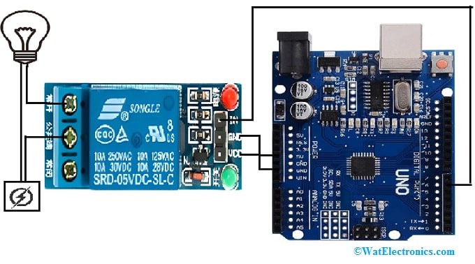
The 5V single-channel relay module interfacing with Arduino is shown below. The interface would be almost the same for the PIC microcontroller as well except that the input pin connection will change as per the pin microcontroller. The required components for this interfacing mainly include a 5V single channel relay module, Arduino uno, power supply, and light bulb. The connections of this interfacing follow:

5V Single Channel Relay Module Interfacing with Arduino
- The VCC pin of the relay module is connected to the 5V pin of the Arduino.
- The GND pin of the module is connected to the GND pin of the Arduino.
- The IN input pin of the module is connected to a digital pin like pin6 of the Arduino.
Connect the module to the AC-powered device like a lamp to control by cutting your live AC line into two ends. One connecting end of the wire to the COM pin & another end to NO/ NC based on your requirement. If you want to keep your device off generally & turn it on irregularly, then the other end of the wire need to be connected to NO or to NC. At first in this interfacing, we want to be off our lamp and after that turn it on once we trigger the relay, thus we need to connect one wire end to COM & the other end to NO.
Code
The required code for the 5V single-channel relay module interfacing with Arduino is shown below.
int RelayPin = 6; //It declares the pin to which the input pin of the module is connected//.
void setup() {
// Set RelayPin as an output pin
pinMode(RelayPin, OUTPUT);// the input pin is configured to perform as an output//
}
void loop() {
// Let’s turn on the relay…
digitalWrite(RelayPin, LOW);// pulls the pin LOW//
delay(3000);
// Let’s turn off the relay…
digitalWrite(RelayPin, HIGH); );// pulls the pin HIGH//
delay(3000);
}
Once the above code is uploaded, the code activates the relay module for three seconds and after that, it deactivates for three seconds so that LED is controlled easily.
Applications
The applications of the 5V single-channel relay module include the following.
- 5V single-channel relay module is used in home automation-based projects to control different loads.
- This module is used for switching an AC voltage load from a low-voltage DC.
- It provides electrical isolation between high & low power sources.
- These modules are used for controlling the speed of motors by start-delta converters.
- These are used in over and under-voltage protection systems.
- These are used in mains switching and high current switching.
- This relay module is used for controlling a load like a motor, solenoid, or lighting system.
- This module can also be used to switch AC/DC voltages.
- These modules are normally used for driving mains loads from Arduino (or) a sensor
- This module is normally used wherever only a single load needs to be switched.
- This module is ideal for different electronics projects & automation applications due to its versatile design & operating voltage.
- This is a very convenient module, used for controlling motors, lamps, AC load & solenoid valves.
Please refer to this link for 5V Single Channel Relay Module Datasheet.
Thus, this is an overview of the 5V single-channel relay module-pin configuration, specifications, interfacing, and its applications. This is a very convenient board used for controlling high current, high voltage loads like solenoid valves, motors, AC loads & lamps. This module is mainly designed for interfacing with any microcontroller like PIC, Arduino, etc. Here is a question for you, what is a two-channel relay module?