A relay module is a type of electrical switch that operates through an electromagnet where this electromagnet can be activated with a low-power signal from any microcontroller. The main function of this relay module is to switch ON/OFF any electrical device or system and also it serves to separate the control circuit from the system or device being controlled. This module is significant because it allows you to use any microcontroller to control loads with very higher currents & voltages. These modules are available in different types & sizes like 5V two channels, three channels, four channels, etc. This article discusses an overview of the 5V eight-channel relay module, its specifications, and its applications.
What is 5V Eight Channel Relay Module?
A 5V eight-channel relay module includes eight relays and also other switching & isolating components to make interfacing with any sensor or microcontroller very easy with minimum components & connections. Every relay on the relay module includes the same circuit & the input GND is very common to all channels. The controlling of these relay modules can be done directly by a variety of microcontrollers like AVR, Arduino, PIC, PLC, ARM, and many more. This module is also capable of controlling different appliances with large currents. These are used in a wide range of applications in the industrial sector, all MCU control, smart home control, PLC control, etc.
Pin Configuration:
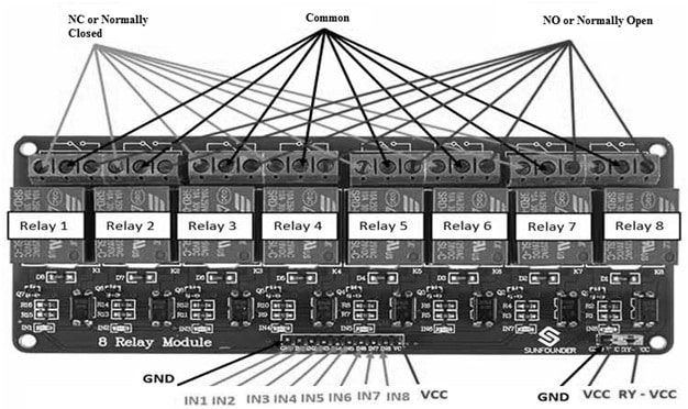
The pin configuration of the 5V eight-channel relay module is shown below. This module includes thirteen pins and each pin and its functionality are discussed below.

5V Eight Channel Relay Module Pin Configuration
- Pin1 (GND): It is a GND reference of the relay module.
- Pin2 (IN1): It is an i/p to first activate the relay.
- Pin3 (IN2): It is an i/p to second activate relay.
- Pin4 (IN3): It is an i/p third active relay.
- Pin5 (IN4): It is an i/p to fourth activate relay.
- Pin6 (IN5): It is an i/p to fifth activate relay.
- Pin7 (IN6): It is an i/p to sixth activate the relay.
- Pin8 (IN7): It is an i/p to seventh activate relay
- Pin 9 (IN8): It is an i/p to eighth activate relay.
- Pin 10 (VCC): It is the power supply pin of the relay module.
- Pin11 (GND): It is the GND reference of the relay module.
- Pin 12 (VCC): It is a power supply selection jumper.
- Pin13 (RY-VCC): It is an alternate power pin of the relay module.
Features & Specifications:
The features and specifications of the 5V eight-channel relay module include the following.
- This relay module includes two contacts One NC (normally closed) & one NO (normally open).
- It includes eight channels.
- It has a power supply indicator & control indicator lamp.
- A standard interface can be used to control directly by different microcontrollers.
- It has Opto-isolated inputs.
- It includes Indication LEDs for providing the output status of the relay.
- Its operating voltage is 5V.
- This relay module is compliant with international security standards, control & load areas isolation trenches.
- Its trigger current is 5mA.
- The current supply for a single relay that is active is 70mA and for all eight relays is 600mA.
- This module size approximately L x W x H is 135mm x 55mm x 20mm.
- This module weight approximately is 56grams.
- The max contact voltage of the relay is 250VAC, 30VDC
- Its maximum relay current is 10A.
- Alternate 5V eight-channel relay modules are; single-channel, dual-channel, and four-channel.
Components
The 5v eight channel relay module includes different components like a 5V relay, male headers, terminal blocks, transistors, diodes, LEDs & optocouplers.
The eight-channel relay module includes 5V eight relays. These modules also include 8 terminal blocks where each block includes six terminals & every block can be shared through two relays. So the terminals of this module are screw type which is used to make connections easy to mains wiring & variable.
In this module, the eight relays are rated with 5V, so that the relay can be activated whenever there are around 5Volts across the coil. On every relay, the contacts are specified on the relay body for 30VDC & 250VAC, and 10A in every case.
The switching transistors on this module perform as a buffer in between the coils of the relay that need the inputs & high currents which don’t draw very much current to amplify the i/p signal so that they can simply drive the relay coils for activating the relays.
The freewheeling diodes on the module avoid voltage spikes across the transistors once the relay is deactivated. The LEDs on the module will glow whenever the respective relay coil is energized & indicates that the relay is active.
The optocouplers on the board form an extra isolation layer between the inputs & the load being switched. The isolation is optional & can be chosen with the VCC selector jumper. Here, the input jumper includes the main VCC, GND & input pins used for simple connection with female jumper wires.
5V Eight-Channel Relay Module Interfacing with Arduino
In a home automation system, these relay modules are used for controlling loads. These relay modules have numerous relay outputs, providing a simple connection to control numerous devices through a single microcontroller.
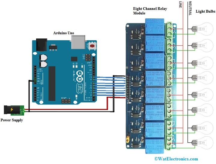
5V eight-channel relay module interfacing with the Arduino board is shown below. The required components of this interfacing mainly include a 5V eight-channel relay module, Arduino Uno, and a power supply. The connections of this interfacing follow as;
The GND pin of the relay module is connected to the GND pin of the power supply & after that to the GND pin of the Arduino. If the GND pins are not correctly connected, then control signals will not be taken into account. The VCC pin of the module is connected to the power supply. The INx pins of the relay module are connected simply to the outputs of the microcontroller.

5V Eight Channel Relay Module Interfacing with Arduino
In this interfacing, eight separate loads like light bulbs are connected to the relay module’s NO terminals. The live wire is connected to each relay’s common terminal. Once the relays are enabled, then the connected load to the live wire is powered. So this setup can be upturned by simply connecting the light bulb to the NC terminal of the relay, which will maintain it switched ON until the relay is turned on.
Code
To make the multi-channel relay module drive, a loop is created on the outputs of the microcontroller to make active or disable the relay. So the following code is the same for two, four, and eight-channel relay modules.
//Constants
#define NUM_DO 4 //8
//Parameters
const int digPin[NUM_DO] = {2, 3, 4, 5}; //{2, 3, 4, 5, 6, 7, 8, 9};
void setup() {
//Init Serial USB
Serial.begin(9600);
Serial.println(F(” Initialize System “));
//Init pwm output
for (int i = 0; i < NUM_DO; i++) pinMode(digPin[i], OUTPUT);
}
void loop() {
for (int i = 0; i < NUM_DO; i++) {
digitalWrite(digPin[i], HIGH);
delay(500);
digitalWrite(digPin[i], LOW);
delay(500);
}
}
Once the eight-channel relay module is connected & the required code is uploaded, the LEDs &relays must turn ON & OFF one after another.
Applications
The applications of the 5V eight-channel relay module include the following.
- These modules are used for switching main loads.
- These are used in battery backup, home automation & high current-based load switching.
- These modules are used in different electronic & electrical circuits.
- These are used in switching, controlling, and protecting circuit & load transfer applications.
- These modules also provide electrical isolation between two electrical circuits.
- These relay modules are used in the industrial sector, controlling of MCU, smart homes & PLCs.
- These are used for controlling solenoids, lamps, motors, bulbs, etc.
- The eight-channel on the relay module is used for switching various loads simultaneously since there are 8 relays on the similar module. So this is very helpful in making a central hub to power several remote loads.
- This relay module is arranged in the main switchboard & other house parts which can be controlled using a microcontroller from a central location.
Please refer to this link for 5V Eight Channel Relay Module Datasheet.
Thus, this is an overview of the 5V eight-channel relay module. This module has eight 5Volt relays with associated switching & isolating components. This module can be interfaced with a microcontroller/sensor easily using minimum components & connections. In this module, every relay has a similar circuit & input GND is very common to all the channels. Here is a question for you, what is four channel relay module?