There are various electrical and electronic components are used in the industrial sector in different applications like resistors, capacitors, transistors, diodes, rectifiers, regulators, relays, amplifiers, transformers, etc. So, relays play a significant role in the electronics industry. Relays are electromagnets that perform like a switch by simply closing or opening their contacts for controlling the flow of current. Relay modules switch ON/OFF electrical devices as well as electronic systems. It is also used to separate the control circuit from the system or device being controlled. Generally, relay modules are used with different microcontrollers to control low-voltage to high-voltage AC & DC devices. There are different types of relay modules available from single channel to 8-channels which are used in different applications based on the requirement. So this article discusses an overview of a 5V dual channel relay module, pinout, specifications, interfacing, and its applications.
What is 5V Dual Channel Relay Module?
A 5V dual channel relay module is an electrically operated and electromagnetic switch that operates with 5V DC. This module takes the input voltage from a logic chip or any kind of microcontroller that gives a digital output signal. These relays are controlled by different microcontrollers directly like AVR, ARM, Arduino, PIC, and many more. Similar to other relays, these 5V dual channel relay modules are also used mainly to turn ON/OFF a circuit.
Pin Configuration:
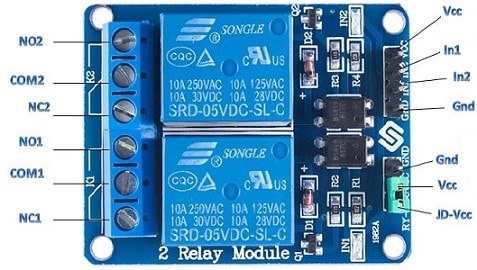
The pin configuration of the 5V dual-channel relay module is shown below.

Two Channel Relay Module Pin Configuration
VCC Pin: This is a power pin used to provide power to in-built optocouplers. This pin is connected to the 5V pin of the Arduino board.
GND Pin: This is a common GND pin.
IN1 & IN2 Pins: These are active low pins that are used to control the dual-channel relay. When these pins are pulled to LOW then it activates the dual channel relay and pulled them high then it deactivates the relay/
JD-VCC Pin: This pin is used to provide a power supply to the electromagnet of the dual channel relay. Whenever the jumper is in position, then this pin is shorted to VCC by allowing the electromagnet to be power-driven through the 5V line of Arduino. So, without using this jumper cap, we have to connect it to a 5V power source separately.
COM Pin: This pin is connected to the device that you want to control.
NC Pin: This pin is usually connected to the COM terminal unless you trigger the dual channel relay that simply breaks the connection.
NO Pin: This is normally an open pin used to connect it to the COM terminal until you trigger the relay.
Features & Specifications:
The features & specifications of the 5V dual-channel relay module include the following.
- It has a high-level trigger mode.
- The standard interface is connected directly connected with microcontrollers.
- It has a standard double-sided solid PCB.
- It is very secure & noise-free.
- It is capable of controlling different appliances & other equipment through a large current.
- It is a two-channel relay board & it can be directly controlled by different microcontrollers.
- The status indicator red color lights are helpful to secure use.
- Its normal operating voltage is 5V DC.
- Its normal current is 70mA
- Its load current maximum is 10A or 30V DC, 10A or 250V AC.
- Its switch voltage maximum is 30V DC, 250V AC.
- Its operating time is ≤ 10ms.
- Its release time is ≤ 5ms.
- Its trigger current is 5mA.
- Once the relay is active the current will be 70mA for a single relay and 140mA for both.
- The maximum current of the relay is 10A.
- The Alternate 5Volts Dual Channel Relay Modules are one-channel, four-channel, and eight-channel relay modules.
- Alternate relay modules which are used for AC switching are; SCRs, SSR (Solid State Relay) modules, and TRIACs.
5V Dual Channel Relay Module Parts
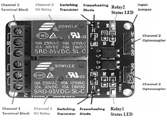
5V dual channel relay module includes different parts which are discussed below.

5V Dual Channel Relay Module Parts
Relays
This relay module includes its specifications which are mentioned on the blue blocks. In this relay, the 5Volts name comes from its SRD-05VDC-SL-C part number because it requires 5Volts only for activating its electromagnet. So, the voltage ratings & maximum current are 250VAC & 10A, and 30VDC for each channel respectively.
I/P Block
In this 5Volts dual channel relay module, the i/p block is located on the right side. This block mainly includes a control pins block above the higher right corner & a power supply jumper on the below right corner of the module.
Control Pins Block
This block includes mainly four pins one Vcc pin to switch on the module, a GND pin & two i/p pins for controlling relays respectively. The Vcc pin provides a 5V supply to the status LED.
Power Supply Selection Jumper
This jumper shows that it permits us to select whether we desire to power up our relay module through an independent power source or a microcontroller. If we want to activate relays by a microcontroller, then the blue color jumper cap must stay intact. So this module will be physically connected to the microcontroller. To make these relays work, the exclusion of the jumper cap commands us to give a separate power source using the JD-Vcc pin. So in this manner, the microcontroller will not be physically connected to the circuit because of its in-built optoisolators.
O/P Block
The output block is located on the left side of the relay module that includes 2-pairs of 3-screw terminals like normally open (NO), normally closed (N.C) & common (C.O).
NO & NC
NC is a normally-closed contact whereas NO is normally-open contact. Once the relay coil is de-energized then NC contact will open & NO contact will close.
Status LEDs
This module includes two SMD-kind status LEDs. Every relay includes its own status LED that enables it whenever its particular relay is strengthened throughout the i/p pin. When it is a 5Volts dual channel module then it will harm the status LEDs when the voltage is above 5 volts.
Freewheeling Diodes
This module includes two freewheeling diodes which are useful for controlling the back emf generated by the relays inductive coils. This emf causes severe harm, thus we require freewheeling diodes to oppose the effect.
Switching Transistors
This module includes more switching transistors & relay modules which will be connected to the relay module. The main function of switching transistors is to increase the flow of current to meet the necessity of the relays. So these transistors control these relays throughout any Arduino or ESP32 or TM4C123 microcontroller by utilizing its low-current GPIO pins. The kind of transistor will decide whether the i/p pins are active low/ high.
Optoisolator ICs
The main function of these ICs is to provide proper isolation in between the DC Circuit as well as the power of dual supply relays for the transfer of the i/p signal without being connected directly.
Interfacing of 5V Dual Channel Relay Module with Arduino Uno Board
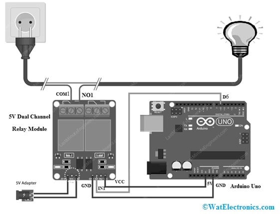
Interfacing of the 5V dual channel relay module with Arduino uno board is shown below. A relay module control through the Arduino board is very easy like an LED control. This is used to turn on the relay for three seconds and after that, it will turn off for three seconds. The required components to make this interfacing mainly include Arduino UNO, type A to B USB cable, two channel relay module, 220V AC bulb, jumper wires, and DC power used for the Arduino Uno board.

Interfacing of 5V Dual Channel Relay Module with Arduino Uno Board
The connections of this interfacing follow as;
- The GND terminal of the relay module is connected to the GND of the Arduino Uno board.
- The IN1 terminal of the relay module is connected to the D6 pin of the Arduino Uno board.
- The VCC terminal of the relay module is connected to the 5V pin of the Arduino Uno board.
- The NO1 terminal of the relay module is connected to the Line of the AC bulb.
- The Neutral of the AC bulb module is connected to the Neutral of AC power.
- The COM1 of the relay module is connected to the Line of AC power.
Working
The working of the 5Volts dual channel relay module with Arduino UNO board is, this module includes 4 control pins. So, pin-1 like a power supply pin is used to provide power to the optocoupler within the module. Pins 2 &3 are used for controlling the dual-channel relay. Pin-4 is a ground pin. Pins 5, 6 & 7 are called power supply selection pins, and pin 8-13 are called o/p terminal pins.
In the interfacing, cut your appliance’s AC line & connect one end of this line to the module’s COM pin. Now, if you want to turn OFF your device mostly, then it has to be connected through the module’s NO pin. But, if you want to turn ON the device normally, then connect it to the NC pin of the relay module. Here, this connection mainly depends on what you require and the resting condition of your device.
Code
int RelayPin = 6;
void setup() {
// Set RelayPin as an output pin
pinMode(RelayPin, OUTPUT);
}
void loop() {
// Let’s turn on the relay…
digitalWrite(RelayPin, LOW);
delay(3000);
// Let’s turn off the relay…
digitalWrite(RelayPin, HIGH);
delay(3000);
}
Once the connections of the above interfacing are made, and then upload the above code into the board. First, in that code, we have clearly stated the pin through which the module’s i/p pin is connected. After that, we described pin-6 as the circuit output. The loop function in the code defines how it turns ON & OFF the device. These devices are used for controlling any AC appliances within your home, office & industrial automation circuits.
Applications
The uses or applications of the 5V dual-channel relay module include the following.
- The dual-channel 5V relay module is used mainly for switching mains-powered loads using the microcontroller pins.
- This module is very helpful in controlling loads like motors, solenoids, or lighting systems.
- It is also used for switching AC/DC voltages.
- These relays are also used broadly by professionals in industrial, home, and commercial power equipment & systems.
- The common dual channel relay applications mainly include robotics, controlling of motor, controlling of light, solenoid, valve, home automation, alarm systems, surveillance systems, mains loads switching, access control systems, battery backup, process control, DIY projects, etc.
- It is used to control different equipment & appliances with a huge current.
Please refer to this link for 5V Dual Channel Relay Module Datasheet.
Thus, this is an overview of the 5V two-channel relay module – features, specifications, interfacing, and its applications. This relay module is similar to a single-channel 5V relay module except for some additional features such as optical isolation. This module can be utilized to switch loads powered by mains from a microcontroller pin. Here is a question for you, what is a single-channel relay module?