A relay is an electromechanical switch that opens & closes the electrical circuits by getting electrical signals using external sources. These switches include a coil that gets an electric signal & changes it to a mechanical action. The contacts of the relay open and close the electric circuit. Generally, relays operate with AC/DC current, at common voltages & the current they can control ranges from 2A to 30A. A relay module is one type of board where a relay is mounted on this board with other electronic components to supply isolation as well as safety. The relay module provides an easy & suitable method to control electrical devices remotely. There are different relay modules with different channels operated with 5V like single channel, dual channel, four-channel, etc. This article discusses an overview of the 5V 4-channel relay module.
What is 5V Four-Channel Relay Module?
A relay module that has four 5V relays with the associated switching, as well as isolating components, is known as a 5V 4-channel relay module. This relay module will make interfacing easy with a sensor or microcontroller. This relay module is a convenient board used mainly for controlling high voltage, high current loads like electrical motors, lamps, AC loads & solenoid valves. This module is mainly designed for interfacing with microcontrollers like PIC, Arduino, etc.
Pin Configuration:
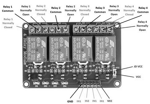
The pin configuration of the 5V 4-channel relay module is shown below. This relay module includes 8 pins which are discussed below.

5V 4 Channel Relay Module Pin Configuration
- Pin1 (GND): It is a GND pin of the module.
- Pin2 (IN1): It is an i/p to activate the relay.
- Pin3 (IN2): It is an i/p to activate relay2.
- Pin4 (IN3): It is an i/p to activate relay3.
- Pin5 (IN4): It is an i/p to activate relay4.
- Pin6 (VCC): It is a power supply pin for the relay module.
- Pin7 (VCC): It is a power supply choice jumper.
- Pin8 (JD-VCC): It is an alternating power pin of the module.
Output Connections:
The output connections of the 5V 4-channel relay module are discussed below.
Common Connection (COM): The common connection of the relay is the center terminal, used within both NC & NO connections.
Normally Open (NO): The NO connection works like a switch. In this connection, there is no contact between the common connection & NO because it is normally open. However, once we trigger the relay module, it will connect to the COM & provides power to the load, which will activate the light. So the circuit will firstly be in open condition until we activate the condition.
NC (Normally Closed): As compared to the NC connection, NO is quite the opposite connection. So it will stay in contact always with COM even if the module is not activated. Once we activate the relay module, it will open the electrical circuit, thus the connection will be lost.
Once you use the relays within the NO connection & the equivalent IN pin is set to LOW, after that the power supplies from the COM & out of the NO connector to power the device.
K1: Connect the load’s one end to the COM whereas the other end is connected to the NO. Similarly, the K2, K3 & K4 connections are the same.
Features & Specifications:
The features & specifications of the 5V 4-channel relay module include the following.
- This module includes four channels.
- This relay module size is L x W x H 75mm X 55mm X 19.3mm.
- Its weight is 61 grams.
- The PCB color of the relay module is Blue.
- This relay module includes four 3.1mm permanent screw holes at every corner of the module.
- It includes one NC contact & one NO contact.
- Its operating voltage ranges from 3.3V to 5V.
- Its trigger current is 5mA.
- The max contact voltage of the relay is 250VAC, 30VDC.
- The Max current of the relay is 10A.
- When the single relay is active then the current is 70mA & 300mA for all four relays.
- It has a high impedance-based controller pin.
- It has a pull-down circuit to avoid malfunction.
- It has an indicator of power supply.
- This relay module is obedient with international security standards, control & load areas isolation channels.
- Alternate relay modules are single-channel, dual-channel, and eight-channel relay modules.
5V 4 Channel Relay Module Components
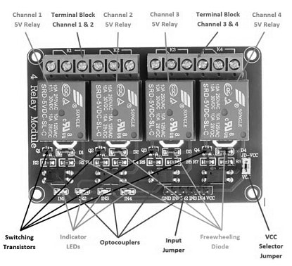
5V 4-channel relay module includes the 4-channel relay module and different components like a relay, switching transistors, indicator LEDs, optocouplers, input jumper, freewheeling diode & VCC selector jumper.

5V 4 Channel Relay Module Components
There are mainly two terminal blocks with six terminals each & every block is divided through two relays. The terminal of this module is a screw type, which makes mains wiring connections simple and variable.
The four relays on the module are activated with 5V when there are around 5Volts across the relay coil. The contacts on every relay body are indicated with 250VAC & 30VDC and 10A.
The switching transistors within the relay module work like a buffer in between the relay coils which require high currents & the i/ps which don’t draw a lot of current. The input signal which is amplified can drive the relay coils for activating them.
The freewheeling diodes in the module avoid voltage spikes across the switching transistors once the 5V relay is turned off while the coils in the relay are an inductive load.
Once the particular relay coil is energized then the indicator LEDs will blink to indicate that the relay module is active.
The optocouplers can form an extra isolation layer between the inputs & also the load being switched. The isolation is elective and can be chosen with the VCC selector jumper. Here, the input jumper includes the input pins, main VCC & GND for simple connection with female jumper wires.
5V 4 Channel Relay Module Interfacing with Arduino
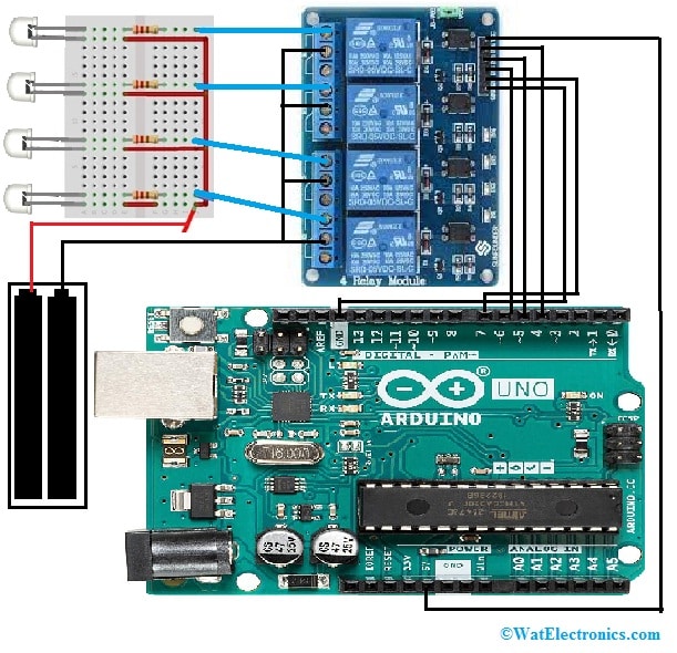
The 4 relay module interfacing with an Arduino is very simple & it allows you to control various A.C & D.C devices with Arduino The load used at the o/p of the relay in this interfacing is an LED & it controls through the Arduino.
The relay module interfacing with Arduino uno is the most useful application for Arduino boards because it is used for controlling both the devices of AC & DC by controlling the relay easily with 5V.
Generally, a relay is a switch that operates electrically through an electromagnet. It is used for controlling high-voltage & low-voltage electronic devices. They work on the electromagnetism principle. Once the electricity is given to the relay coil, it functions like a magnet & adjusts the switch condition.
The 5V 4-channel relay module interfacing with Arduino is shown below. The required components to make this interfacing mainly include Arduino Uno, a breadboard, 4 channel relay module, a 3volts battery, 220-ohm resistors, and LEDs.
The connections of the 5V 4-channel relay module with Arduino follow as;

5V 4 Channel Relay Module Interfacing with Arduino
- Connect the Arduino board’s 5v pin to the VCC pin of the 4 relay module.
- The Arduino board’s GND pin is connected to the GND pin of the relay module.
- The communication pins of relay modules like IN1, IN2, IN3 & IN4 are connected to the data pins 4, 5, 6 & 7 of the Arduino board.
- The positive terminal of the battery is connected to the positive terminal of the led.
- The negative terminal of the battery is connected to the COM of every relay & the NO is connected to the LED’s negative pin.
Code
#define RELAY1 7
//Defining pin 7 of the Arduino for the 4 relay module
#define RELAY2 6
//Defining the pin 6 of the Arduino for the 4 relay module
#define RELAY3 5
//Defining the pin 5 of the Arduino for the 4 relay module
#define RELAY4 4
//Defining the pin 4 of the Arduino for the 4 relay module
void setup() {
pinMode(RELAY1, OUTPUT);
//Defining pin 7 of the Arduino as output
pinMode(RELAY2, OUTPUT);
//Defining pin 6 of the Arduino as output
pinMode(RELAY3, OUTPUT);
//Defining pin 5 of the Arduino as output
pinMode(RELAY4, OUTPUT);
//Defining pin 4 of the Arduino as output
}
void loop()
{
digitalWrite(RELAY1,LOW);
// This will Turn ON relay 1
delay(5000);
// Wait for 5 seconds
digitalWrite(RELAY1,HIGH);
// This will Turn the Relay Off
digitalWrite(RELAY2,LOW);
// This will Turn ON the relay
delay(5000); // Wait for 5 seconds
digitalWrite(RELAY2,HIGH);
// This will Turn the Relay Off
digitalWrite(RELAY3,LOW);
// This will Turn ON the relay
delay(5000);
// Wait for 5 seconds
digitalWrite(RELAY3,HIGH);
// This will Turn the Relay Off
digitalWrite(RELAY4,LOW);
// This will Turn ON the relay
delay(5000);
// Wait for 5 seconds
digitalWrite(RELAY4,HIGH);
// This will Turn the Relay Off
}
The above code is for the 4-relay module interfacing with the Arduino. Every relay in the module will activate for 5 sec and after that, it will turn off. Once their position changes from ON to OFF/OFF to ON then we can hear a click sound. Once the relay is turned ON then the RED LED will light up on the module.
Applications:
The applications of the 5V 4-channel relay module include the following.
- The 4 Channel Relay Module is very convenient to use in controlling high current, high voltage loads like solenoid valves, motors, AC loads & lamps.
- These relay modules are mainly designed for interfacing with different microcontrollers like PIC, Arduino, etc.
- This relay module is used for controlling various equipment with a huge current.
- These modules can also be used for switching AC/DC voltages
- These modules are used for mains load switching, battery backup, home automation & high current load switching.
Please refer to this link for 5V 4 Channel Relay Module Datasheet.
Thus, this is an overview of the 5V 4 Channel Relay Module, pin configuration, specifications, interfacing, and its applications. This is a convenient board so used for controlling high voltage and high current electrical loads. This relay module is mainly designed for interfacing with different microcontrollers like PIC, Arduino, etc. This relay module can be directly controlled with 3.3Volts/5Volts logic signals from a microcontroller. Here is a question for you, what is a 5V 2-channel relay module?