Generally, we interface a single button, switch, or key with a microcontroller using a single GPIO pin. However, if we want to interface several 9 or 12, or 16 keys, then it requires various microcontroller GPIO pins. To save some of the microcontroller GPIO pins, we can utilize a 4×4 keypad module. This module includes keys that are arranged within rows & columns. So, if we desire to interface 16 keys with a microcontroller then we need 16 GPIO pins although if we utilize a 4×4 matrix keypad then we need the microcontroller’s 8 GPIO pins only. So this article discusses an overview of a 4×4 keypad module, it’s working & its Applications.
What is a 4×4 Keypad Module?
The 4×4 keypad module is an input device, used to provide input value within a project. This module includes a total of 16 keys which provide 16 input values. These matrix keypad modules are made with flexible membranes & thin material. The 16 keys in this module are arranged in a matrix of columns & rows. All these are linked to each other through a conductive trace. Generally, there is no link in this keypad between rows & columns. Once we push any key in the matrix keypad, then a row & a column in this keypad will make contact, or else; there is no link in the matrix keypad between rows & columns.
Specifications:
The specifications of the 4×4 keypad module include the following.
- The type of product is a 4 X 4 keypad module.
- The rating of voltage Max is 24V DC.
- The rating of the current Max is 30 mA.
- The operating range of temperature is 0 to 50 °Centigrade or 32 to 122 °F.
- It includes 8 pins.
- The dimension of the keypad is 6.9 cm X 7.9 cm.
- The dimension of the cable is 2.0 cm X 8.8 cm.
- This matrix keypad design is Ultra-thin.
- The key layout is 4 rows x 4 columns.
- The type of key is the membrane.
- Its operating voltage ranges from 3V to 5V DC.
- The connector used is a Female 2.54mm Pitch.
Pin Configuration:
The pin configuration of the 4×4 keypad module includes the following.

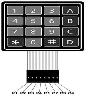
4×4 Keypad Pin Configuration
- Pin1 (R1): This pin is taken out from the first row.
- Pin2 (R2): This pin is taken out from the second row.
- Pin3 (R3): This pin is taken out from the third row.
- Pin4 (R4): This pin is taken out from the fourth row.
- Pin1 (C1): This pin is taken out from the first column.
- Pin2 (C2): This pin is taken out from the second column.
- Pin3 (C3): This pin is taken out from the third column.
- Pin4 (C4): This pin is taken out from the fourth column.
4×4 Keypad Module Working
A 4×4 keypad includes a total of eight connections, where four connections are connected simply to the column & the remaining connections are connected to the rows. Once a button in the matrix is pushed, a connection between one of the columns & rows can be established.
To detect a pushed key, the microcontroller will ground all the rows in the matrix by simply providing zero to the o/p pins, after that it reads the columns in the matrix. If there is no key is pushed, then the data read in the matrix from the column will be 1111.
Once we push a button in the matrix then it shorts the row lines to column lines by allowing the flow of current between them. So for instance, when key1 is pushed then row 1 & column 1 will be shorted.
If the C1 bit value (first column) is ‘0’, the key button1 is pressed. So, for instance, if C1 C2 C3 & C4 = 0111, then a key within column C1 has been pushed. Thus, this procedure will continue for all rows as well as columns.
When a button is pressed in the matrix keypad, the microcontroller reads these lines like the following.
- The microcontroller first sets all the row & column lines in the keypad to input.
- After that, this microcontroller will set a row to LOW.
- It verifies the one-column line at a time.
- If the connection of the column is HIGH, then the row button has not been pushed.
- If this connection goes LOW, then the microcontroller identifies which row on the matrix is set to LOW & which column line was noticed to LOW once verified.
- Lastly, it recognizes which button on the keypad was pushed and that corresponds to the detected column & row.
4×4 Keypad Module Interfacing with Arduino Uno & LCD
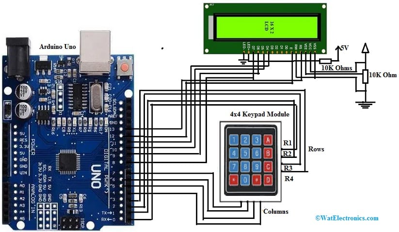
The 4×4 keypad module interfacing with Arduino Uno & LCD is shown below. A 4×4 keypad module is used for entering passwords, dialing a number, browsing through menus &also even controlling robots. These 4×4 keypads can be observed in Telephones, Security Systems, and ATMs, to provide i/p data to the security system by the user. These keypads can also be utilized with Microcontrollers as well as Arduino platforms to execute different projects.
Here we are going to discuss how a 4×4 Matrix Keypad is interfaced with Arduino to obtain the keypad data. The required components for this interfacing mainly include Arduino UNO, 4×4 matrix keypad, 16×2 LCD display, 10KΩ, 1KΩ resistor, power supply, potentiometer, connecting wires, and breadboard.
The connections of this 4×4 keypad module interfacing with Arduino & LCD follow as;
- First, the keypad Rows are connected to the Digital Pins from 0 to 3 of the Arduino board.
- In the same way, the Keypad Columns are connected to Arduino Digital Pins from 4 to 7.
- The extra component like 16×2 LCD’s data pins are connected to Arduino’s digital pins from 8 to 11.
- The 16×2 LCD’s RS & E Pins are connected to Arduino’s Pins 12 & 13.

4 x4 Keypad Module Interfacing with Arduino & LCD
Code
#include <Keypad.h>
#include <LiquidCrystal.h>
const byte ROWS = 4; //four rows
const byte COLS = 4; //four columns
//define the cymbols on the buttons of the keypads
char hexaKeys[ROWS][COLS] = {
{‘1′,’2′,’3′,’A’},
{‘4′,’5′,’6′,’B’},
{‘7′,’8′,’9′,’C’},
{‘*’,’0′,’#’,’D’}
};
byte rowPins[ROWS] = {0, 1, 2, 3}; //connect to the row pinouts of the keypad
byte colPins[COLS] = {4, 5, 6, 7}; //connect to the column pinouts of the keypad
//initialize an instance of class NewKeypad
Keypad customKeypad = Keypad( makeKeymap(hexaKeys), rowPins, colPins, ROWS, COLS);
LiquidCrystal lcd(13, 12, 11, 10, 9, 8);
void setup()
{
lcd.begin(16, 2);
lcd.print(“Electronics Hub”);
delay(2000);
lcd.clear();
lcd.setCursor(0, 0);
}
void loop()
{
char customKey = customKeypad.getKey();
if (customKey)
{
lcd.print(customKey);
}
}
Working
The main objective of this 4×4 Matrix Keypad interfacing to Arduino is to know how this Interface works & how to verify the pressed key on the matrix keypad to display it over the 16×2 LCD. To verify the pressed Key above the Keypad, a special “Keypad” library is used. First, you must download this library from the Arduino site & place it within Arduino/libraries directory. This library was simply developed by Alexander Brevig & Mark Stanley.
Once the library is installed, then you can easily copy the code given above & upload that code to the Arduino board. So in this code, the 4×4 Matrix keypad keys are simply mapped through 0 to 9 digits, symbols like * & #, and also A, B, C & D alphabets. Therefore, when a matrix keypad key is pressed, the Arduino board detects the key with the “Keypad” library & displays it on the LCD Display.
The Arduino keypad interfacing is used in a wide range of applications like a calculator based on Arduino, door lock systems with passwords, home automation & home security systems.
Advantages
The advantages of a 4×4 keypad module include the following.
- These modules have an Ultra-thin design.
- They have an adhesive backing.
- These modules are interfaced very easily.
- They have a long life.
- Its appearance is artistic.
- These are available in small sizes.
- These are lightweight.
- It is damp-proof, oil-resistant, dustproof, strong sealing vibration-proof & acid-resistant.
Applications
The applications of the 4×4 keypad module include the following.
- 4×4 keypad modules are applicable in security systems, control systems in industries, access control systems, electronic projects, data entry systems, robotics, etc.
- These are used in door safety systems protected by passwords, EVM, musical keypads, remote control robots, etc.
- These are used in various DIY Projects.
- These are used in Industrial machines, vending machines, measuring instruments, engineering systems, data entry in embedded systems, etc.
Please refer to this link for the 4×4 Keypad Module Datasheet.
Thus, this is an overview of a 4×4 keypad module that includes buttons that are arranged in vertical & horizontal fashion. For instance; a 4×4 Keypad includes 16 keys/buttons which are arranged in four rows & four columns. Here is a question for you, what is a 4×3 Keypad?