2n5401 PNP transistor is used in different general-purpose electronic applications. These transistors are very helpful wherever the load is connected with the transistor and consume low current, although it works on high voltage. This PNP transistor can also be used frequently in telephone circuits, or any electronic circuits wherever you desire to build a simple switching application (or) amplification with high voltage. This transistor is also used as a general-purpose transistor to control LEDs, relays, etc. This article discusses an overview of a 2N5401 PNP transistor – pin configuration, specifications, circuit & its applications.
What is a 2N5401 PNP Transistor?
2N5401 is a PNP transistor particularly designed for a high voltage less power switching applications which mean the current drawn or used by the load is low. This transistor is available in TO-92 and SOT54 packages.
This transistor includes three terminals like emitter, base & collectors. At the base side terminal, a small current is applied to control the huge current at the remaining two terminals. It is a bipolar junction transistor (BJT) where conduction is performed through both electrons & holes however the majority of charge carriers in this transistor are holes.
In this type of transistor, the ‘P’ side signifies the positive polarity at the emitter terminal whereas the ‘N’ side signifies the negative polarity at the base terminal. This is also known as an amplifier transistor because it comes with 150V of collector-emitter voltage & frequently used for amplification purposes. To operate this PNP transistor correctly within the circuit, it doesn’t need external components. This transistor exhibits thermal shutdown & current limiting which makes the device considerably rugged.
Pin Configuration:
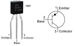
The pin configuration of the 2N5401 pnp transistor with a symbol is shown below. This transistor includes three terminals where each pin and its function are discussed below.

2N5401 PNP Transistor Pin Configuration
- Pin1 (Emitter): It is an emitter terminal that allows the flow of current to the device through this pin.
- Pin2 (Base): It is a base terminal, used to trigger transistors ON & OFF.
- Pin3 (Collector): It is a collector pin where the current flows out from this pin.
Features & Specifications:
The features and specifications of the 2N5401 pnp transistor are listed below.
- The type of transistor is PNP.
- The type of available package is TO-92.
- The maximum collector current or IC is 600mA.
- The maximum emitter-base voltage or VEB is 5V.
- The maximum collector base voltage or VCB is 160V.
- The maximum collector-to-emitter voltage or VCE is 150V.
- Number of terminals -3
- The terminal finish is made with Tin/Lead (Sn/Pb).
- Single element configuration.
- The transition frequency is 100MHz.
- Max power dissipation is 0.62 W.
- Maximum collector dissipation or Pc is 600 mW.
- Maximum transition frequency or fT ranges from 100 to 300 MHz.
- DC Current Gain or hFE ranges from 50 to 240.
- Maximum operating temperature ranges from -65 to +150 C.
2N5401 PNP Transistor Circuit
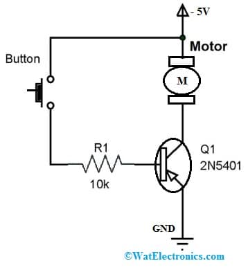
The circuit diagram of the 2N5401 PNP transistor is shown below. This circuit can be designed with a button, 2N5401 transistor, motor, 10k resistor, and -5V supply. In this circuit, the 2N5401 transistor is used as a simple switching device, the switching load being used is a small DC motor the button in the circuit is used to trigger the transistor & 10KΩ resistor is used for restricting the current flow to the base terminal & also avoids allowed breaching maximum voltage at the base terminal. This circuit is powered with a -5V DC.

2N5401 PNP Transistor Circuit
Working
This circuit works in two cases one is when the button is not pressed and the second one is when the button is pressed. When the button in the circuit is not pushed, there will be no base current, the transistor will not conduct. So whenever the transistor in this circuit does not conduct then the whole voltage will emerge across it & the motor in the circuit will be turned OFF.
When the button in the circuit is pushed, the base terminal of the transistor will be connected to the negative supply thus there will be a path for the flow of current. Once the current at the base terminal supplies out from the device then the transistor will conduct. In the presence of this current flow at the collector terminal, a voltage appears across the connected motor in series with the collector terminal. In the presence of the voltage, the motor in the circuit will start revolving & it will wait until the button in the circuit is released. When the button is released at one second the current at the base terminal reaches zero so that the transistor will make the motor turn OFF.
By using the above circuit, we can control the motor by turning ON & OFF with a simple button as a trigger & transistor as a switching device. Do you wonder why one should use a transistor to control a motor why not directly a normal switch can control ?
The reasons are:
- Current amplification: A transistor can act as a current amplifier, allowing a small current from a switch to control a large current flowing to the motor. this means that a low-power switch can control a high -power motor, which can be very useful in many applications.
- Switching speed: Transistors can switch on and off very quickly, allowing for precise control of the motor’s speed and direction. This is especially important in application that require rapid changes in motor speed or direction such as robotics or automation systems.
- Protection: Using a transistor to control the motor can help protect the switch from damage caused by high currents and voltage spikes that can occur when the motor is turned on or off. The transistor can act as a buffer, isolating the switch from the motor and preventing electrical noise from interfering with the switch operation.
- Efficiency: A transistor can modulate the motor’s power supply, reducing energy consumption and prolonging the life of the motor.
Equivalent & Replacement Transistors
The equivalent 2N5401 pnp transistors are 2N5551 (NPN), MPSA93, MPSA92, 2N5096 & BF723. The replacement 2N5401 pnp transistors are; KTA1275, 2SA1319, 2SA1625, 2SA1207, 2SA1625, 2SC2909, etc. But before replacing these transistors, you have to cross-check their pin configuration, because some of them may have different pin configurations.
How to use a 2N5401 PNP Transistor Safely in a Circuit?
To use the 2N5401 pnp transistor securely within a circuit to obtain long-term performance, this transistor should operate a load above 600mA and not operate a load above 150V. Always better to use an appropriate base resistor through the transistor. Avoid wrong connections in the electronic circuits otherwise, it will get damaged & always store this transistor in the temperature range from -65 C to +150C.
Applications
The applications of the 2N5401 pnp transistor include the following.
- This voltage transistor is used in any type of high-voltage application where the load consumes less current.
- This transistor can also be utilized in low voltage-based applications for instance 30Volts, 40Volts, or 50Volts, etc.
- The transistor with 600mA of collector current can be used for driving or controlling LEDs, big relays, high power-based transistors & other loads which need below 600mA of current.
- It is used in normal voltage & high voltage circuits for amplification.
- It is used for switching in normal & high voltage-based circuits which have the capacity to switch loads below 600mA.
- It is used in Telephony applications.
Please refer to this for How to Select a Transistor.
Please refer to this link for the 2N5401 PNP Transistor Datasheet, IRF3205 MOSFET Datasheet.
Thus, this is an overview of the 2N5401 PNP Transistor – circuit, working with applications. This transistor is mainly employed where load uses extremely less power like high voltage-based applications. This type of PNP transistor can also be utilized when you need a simple switching device in high-voltage loads. Here is a question for you, what is the high voltage of this transistor?