The 2N4401 transistor is a through-hole component, manufactured by Multicomp Pro and is mainly designed for general-purpose amplifier and switching applications. This transistor belongs to the NPN family with a silicon planar epitaxial structure which provides simple integration into different electronic circuits. This transistor appears as a cornerstone within electronic design by delivering a potent blend of performance & versatility. Its specifications and applications will empower enthusiasts and engineers to influence its powers in many electronic circuits. This article discusses an overview of the 2N4401 transistor, pinout, features, specifications, and applications.
What is a 2N4401 Transistor?
The 2N4401 is an NPN transistor, available in a compact TO-92 (TO-226) metal package and commendable features. It is used frequently in various applications as a switch and a medium-power amplifier. This transistor includes three terminals; emitter, base, and collector, and three layers (N-doped, P-doped & N-doped), where the P-doped layer is positioned strategically in between the remaining two N-doped layers.
Whenever a voltage supply or current supply is given at one pair of terminals, it controls the flow of current through the other pair of terminals because the output power is higher compared to the input power.
The 2N4401 transistor comes in three configurations: CB, CE, and CC, but the CE configuration is mostly used for amplification to provide the required voltage and power gain. The CE configuration enhances the input signal by 20dB, which is almost 100 times greater than the input signal. The current at the emitter terminals is a combination of the current at the base and collector terminals. The emitter and collector can be easily distinguished by their dimensions and doping concentration; the emitter is highly doped while the collector is lightly doped.
While looking for a suitable transistor for your application based on a few factors, it is very important to look into a few points on How to Select a Transistor.
Working
The 2N4401 transistor works by holding the base pin at GND, which reverses biases or leaves the emitter and collector terminals open. When a signal is applied to the transistor’s base pin, it forward-biases or closes.
Once this NPN transistor completely biases, it allows a maximum current of 800mA to supply across the emitter and collector terminals, so this stage is known as the Saturation Region. The typical voltage permits across the base-emitter or collector-emitter range from 200 to 900 mV correspondingly. Whenever the base current detaches, the transistor will become completely off, so this stage is known as the Cut-off Region, and the Base Emitter voltage will be approximately 660 mV.
This transistor determines the amplification factor based on its 500 gain values. The collector terminal can supply a maximum current of approximately 800mA, so we cannot connect loads that require more than 500mA. To bias this transistor, restrict the current supplied to the base pin to 5mA.
2N4401 Transistor Pin Configuration:
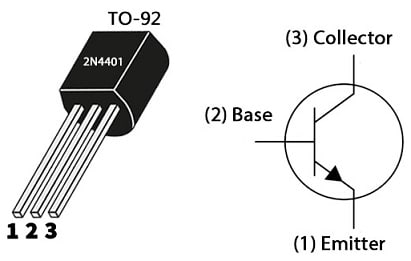
The 2N4401 transistor pin configuration is shown below. This transistor includes three terminals which are discussed below.

2N4401 Transistor Pin Configuration
- Pin-1 (Emitter): The current supply drains out throughout this terminal and is connected normally to GND.
- Pin-2 (Base): This terminal controls the transistor biasing by turning ON/OFF the transistor.
- Pin-3 (Collector): This terminal allows the current flow and is connected normally to load.
Features & Specifications:
The features & Specifications of the 2N4401 Transistor include the following.
- 2N4401 is a three-terminal NPN transistor.
- It is available within the To-92 Package.
- It uses very advanced process technology.
- It has less error voltage.
- It has full voltage operation.
- High DC Current Gain or hFE is typically 80 @ IC=10mAmps.
- Sustained Collector Current or IC is 500mA.
- Its collector current maximum is 600 mA.
- Its collector-to-emitter voltage or VCE is 40 V.
- Collector to base voltage or VCB is 60V.
- The emitter to base breakdown voltage or VBE is 6V.
- Its power dissipation is 625 mW.
- Its transition frequency is 100MHz.
- Its DC gain or hFE ranges from 20 – 300.
- Its storage and operating temperature ranges from -55 to +150 C.
Equivalent & Complementary Transistors
2N4401 equivalents are; 2N2222, 2N3904, P2N2222A, BC547, ECG123AP, BC538, BC537, BC549, BC639, BC636, 2N2369, 2N3906, 2N3055, 2N551 and 2SC5200. 2N4401 complementary transistor is 2N4403 PNP transistor.
Replacing a suitable transistor in any circuit based on requirement is very important. To know how to replace it, please refer to this; Replacing Transistors in Electronic Circuits: Factors and Considerations.
How to use the 2N4401 Transistor in a Circuit Safely for a Long Time?
Every transistor has drawbacks and crossing these will cause the system to break down, so we suggest always utilizing the transistors within their limitations. To securely run this 2N4401 transistor, you should not operate it at more than 40V. You have to use a suitable resistor to provide the necessary base current not operate any load at more than 500mAmps and always operate or store at more than -55 centigrade and less than +150 centigrade
Cold Sensor Switch Circuit
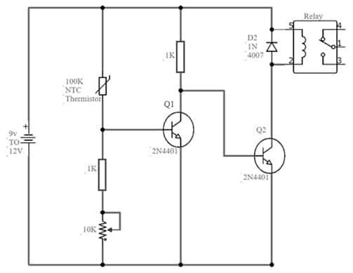
The circuit below shows a cold sensor switch using the 2N4401 transistor and NTC thermistor. This simple circuit is extremely sensitive, so it can mainly sense low or cold temperatures. It activates any connected device with the relay at your preferred low temperature or coldness. The NTC thermistor can sense temperature and its resistance depends on the temperature. Whenever the temperature increases, its resistance decreases, and at low temperatures, its resistance increases.
The required components to, make this cold sensor circuit mainly include; a 9 to 12V DC supply, 100K thermistor, 1K resistors-2, 2N4401 transistors-2, 12V relay, 1N4007 Diode, and 10K variable resistor. Connect the circuit as per the diagram shown below.

Cold Sensor Switch Circuit
Working
This cold sensor switch circuit operates from 9V to 12V. The 100K thermistor detects the temperature in this circuit, and it mainly uses 2N4401 transistors as switches. At first, the thermistor resistance at high temperatures will be least and it will make the circuit turned off. Whenever the thermistor’s resistance is high the temperature will be low and it will make the transistor activate. Now the Q1 transistor will provide 0.7V at the base terminal of the Q2 transistor which activates and turns ON the relay.
The sensor switch circuit uses a potentiometer or 10K variable resistor to regulate and turn on the relay at your preferred low temperature. So this relay must have a similar value to the input voltage. As we have a relay switch at the output of this sensor switch circuit, you can easily connect any load to drive it at your preferred temperature.
Connecting a base resistor to the base terminal of the transistor is mandatory to avoid it being damaged. Please refer to this link for; Choosing Base Resistance for Transistors in Electronic Circuits.
Sensitive Microphone Circuit
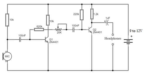
The sensitive microphone circuit is shown below that boosts weak sounds from a distance. So it is quite a sensitive circuit and provides very good gain for weak audio signals. This is a small circuit that uses only two transistors as well as some passive components. This circuit is suitable for the amplification process of an inexpensive sound within electronic projects.
The required components to make this sensitive microphone circuit mainly include; a 9-12V battery, electrets microphone, resistors like; 620K, 10K, 220K, and 1.2K, two 2N4401 transistors, headphones, 20K variable resistors, two 100nF ceramic capacitors and 1µF electrolytic capacitor. Connect this circuit as per the diagram shown below.

Sensitive Microphone Circuit
Working
This sensitive microphone circuit operates with a 9 to 12-volt battery. So, you design this simple circuit using two Q1 & Q2 NPN transistors. You separate these transistors into two different stages, like a mic preamp circuit with high gain and a single-transistor amplifier.
A 620K resistor provides negative feedback to the Q1 Transistor, setting it up similarly to an NPN transistor. The Q1 transistor adjusts its output using a 20K variable resistor, and then passes it on to the Q2 transistor. The second stage also follows a similar procedure for added amplification. The Q2 output employs a capacitor to block the DC voltage of the second transistor. It can now transmit the amplified signal through headphones.
The above circuit incorporates the use of an Electret mic to transmit weak audio signals, which are then amplified on the primary stage through a preamp circuit. The output of the electret mic combines with a 100nF capacitor to remove any DC material present in the audio transmission. Additionally, it uses a 10 K resistor to provide the necessary biasing for the microphone.
Please refer to this link for the 2N4401 transistor datasheet.
Difference between 2N4401 and 2N3904 Transistors
The difference between 2N4401 and 2N3904 transistors is discussed below.
|
2N4401 |
2N3904 |
| 2N4401 transistor is designed mainly to be used as a medium power switch and amplifier, | 2N3904 transistor is designed for low power and current, medium voltage, and operates at fairly high speeds. |
| It operates with 6V at 50mA. | This transistor operates with 40 V at 200 mA. |
| It is available in TO-92 (TO-226) common package | 2N3904 is available in TO-92, SOT223 and SOT23 packages. |
| This transistor’s collector current is around 500mA. | This transistor’s collector current is around 200mA. |
| Its maximum DC gain is 500 and the minimum is 100. | Its DC gain maximum is 300 and minimum is 30. |
| This transistor’s transition frequency is 100 MHz. | This transistor’s transition frequency is 300 MHz. |
| It is not optimized at a low current for operation. | It is better optimized at a lower current for operation as compared to 2n4401. |
| Its maximum collector current is 0.6 amps. | Its collector current maximum is 0.2 Amps. |
| The maximum operating temperature is 150 °C. | Its max operating temperature is 175 °C. |
Advantages & Disadvantages
The advantages of the 2N4401 transistor include the following.
- 2N4401 transistor is a versatile component.
- It can be used as a switch and an amplifier.
- It is an adaptable component.
- This is a robust transistor.
- It can bear a broad range of temperatures and has high resilience to electrical noise, founding itself as a reliable component in different electronic systems.
- It is capable of handling high power and current.
- This transistor has a fast switching speed.
- It has the current handling capability as compared to the BC547.
- It provides a viable alternative with higher current demands within various applications.
The disadvantages of the 2N4401 transistor include the following.
- It is not suitable for high-power applications like systems that need high power.
- It is sensitive to environmental conditions
2N4401 Transistor Applications
The applications of the 2N4401 transistor include the following.
- The 2N4401 transistor extensively used in electronic circuits like sensor circuits, amplifier stages, and audio preamplifiers to showcase its ability within signal amplification.
- This transistor does extremely well in switching loads <500mAmps, motor speed control, and in Darlington pairs applications for superior current gain.
- It is suitable in radio frequency circuits <250MHz and compatible with rectifier and inverter circuits.
- It is a fundamental building block within a variety of electronic systems that provides reliability and flexibility across a range of applications.
- These transistors are helpful in motor speed control.
- Used in RF circuits below 250MHz.
- Rectifier and inverter circuits use these.
- It is used in a variety of switching scenarios.
- You can replace this transistor with other popular transistors like 2N3904, BC547, or 2N2222.
- It drives different loads within electronic circuits like high-power LEDs, transistors, and relays that are below 600mA.
- It can also be used in audio amplifier stages and audio preamplifier circuits.
- You can use it at the output of small audio amplifiers to enhance the output for driving small speakers that operate from 200mW to 2W.
Thus, this is an overview of the 2N4401 transistor, pinout, specifications, circuit, working, and applications. The amplification factor beta represents this transistor’s forward current gain (ß). It is the ratio between base current and collector current. This factor measures the amplified current and its value ranges from 20 to 1000. It is a unitless ratio of both currents. Alpha (α) represents the transistor’s current gain and is the ratio between emitter and collector current. These values mainly range from 0.95 to 0.99, which many frequently consider as one. Here is a question for you, what is 2N222A transistor?