The 2N3904 transistor is a prevalent NPN type BJT (bipolar junction transistor), introduced in the year 1960 by Motorola. This transistor is commonly used as a general-purpose switch and an amplifier within electronic circuits. So it has become one of the most widely used transistors due to its low cost, availability & versatility. This transistor was manufactured by different semiconductor companies worldwide in a range of different packages & specifications like; Diodes Inc, ON Semiconductor, NXP Semiconductors, NXP Semiconductors, Micro Commercial Components, Fairchild Semiconductor and Central Semiconductor Corp. This article covers everything about the 2N3904 transistor which includes pin configuration, features, specifications & its applications.
What is a 2N3904 Transistor?
2N3904 is an NPN general-purpose, low-power, and small signal transistor, used mainly for switching & signal amplification purposes. This transistor is made up of silicon (Si) material and its main functional region is enclosed within the TO-92 package. It is the most frequently utilized bipolar junction transistor due to its low cost, smaller size & wide availability. It is less responsive to variation within voltages & currents. This transistor can bear medium voltage, low amount of current & lower power levels.
This transistor’s dynamic range has >100mA current handling capability for switching applications & a 100MHz frequency handling ability for amplification applications. 2N3904 transistor is used mostly by hobbyists & electronic students in their electronic projects and also in commercial electronic products.
This transistor’s maximum collector current is 200mAmps thus it can drive loads < 200mA within their electronic applications. In addition, the 2N3904 transistor can also work well as an amplifier. The whole device dissipation will be 625 mW which can also be utilized for RF & audio signal amplification purposes.
While looking for a suitable transistor for your application based on a few factors, it is very important to look into a few points on How to Select a Transistor.
Working
The working of this 2N3904 NPN transistor is, that whenever the base terminal is connected to the GND terminal the remaining two terminals will be left open or reverse-biased. Likewise, whenever a signal is provided to the base terminal then it will be forward-biased.
This transistor’s high gain value is 300 which decides the amplification capacity of the transistor. The highest current supply through the collector is 200mAmps, thus the loads that use >200mA current cannot be connected using this transistor. When the current supply is provided to the base terminal, then this transistor can be biased. So this base current should be limited to 5mAmps.
When the 2N3904 transistor is biased completely then it allows 200mA of a maximum current to supply across the two emitter and collector terminals known as saturation region. The allowed typical voltage across the CE or CB terminals could be 40Volts and 60Volts respectively. Once the base terminal current is removed then this transistor will be deactivated which is called the cut-off region, so the VBE could be around 600 mV.
2N3904 Transistor Pin Configuration:
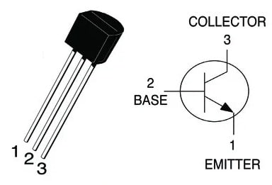
The pin configuration of the 2N3904 transistor is shown below. This transistor includes three pins which are discussed below.

2N3904 Transistor PinOut
- Pin-1 (Emitter): This terminal is denoted with ‘E’ which Drains out the current flow.
- Pin-2 (Base): This is denoted with ‘B’ which helps in controlling the transistor biasing.
- Pin-3 (Collector): It is denoted with ‘C’ which allows the current supply.
Features & Specifications:
The features and specifications of the 2N3904 transistor include the following.
- The max tolerable CE voltage or Vceo is 4V.
- The max tolerable voltage across CB or Vcbo is 60V.
- The maximum allowable CE current is 200mA.
- Collector to emitter max breakdown voltage is 40V.
- The base-to-emitter max breakdown voltage is 6V.
- The minimum required current to keep the transistor base activated is 50nA.
- The minimum required current to keep the collector load activated is 50nA
- The forward current gain or hFE ranges from 100 to 300.
- The amount of minimum voltage necessary to activate the collector terminal is 0.2V.
- The amount of minimum voltage necessary to activate the base terminal is 0.65V.
- Total Power Dissipation is 625 mW
- Its operating junction temperature ranges from -55 to 150 °C.
- CE saturation voltage is 0.2 V.
- BE saturation voltage is 0.65 V.
- DC gain ranges from 100 to 300.
- The collector’s current maximum is 200 mA.
- The transition frequency is 250 MHz.
- Input capacitance is 8 pF.
- Output capacitance is 4 pF.
- Reverse transfer capacitance is 1.2 pF.
Equivalent & Complementary Transistors:
The equivalent or replacements of 2N3904 transistors are; S8050, 2N2222, 2N4401, SS9013 and BC537. The complementary 2N3904 transistor is 2N3906.
Replacing a suitable transistor in any circuit based on requirement is very important. To know how to replace it, please refer to this; Replacing Transistors in Electronic Circuits: Factors and Considerations.
How to use the 2N3904 Transistor in a Circuit Securely for Long Time?
To use the 2N3904 transistor for the long term in a circuit securely, it is recommended to not drive any load >100mA. An appropriate base resistor must be used always and should not provide CE voltage > 40V. Always operate (or) store this transistor in temperatures > -55 centigrade & < +150 centigrade.
How to use a 2N3904 Transistor in a Circuit?
To use the 2N3904 transistor in a basic circuit, the following rules must be followed.
Determine the Transistor Terminals:
The 2N3904 transistor includes three terminals the emitter, base, and collector where the emitter terminal is connected to GND and the collector terminal is connected simply to the load like a speaker or an LED.
Decide the Operating Conditions:
The operating conditions of this transistor like voltage & current levels should be decided based on the circuit requirements.
Determine the Base Resistor:
The base resistor in the circuit restricts the flow toward the base terminal, which changes the current flowing throughout the collector terminal. So to calculate this resistor’s value, Ohm’s Law is used like RB = (VCC – VBE) / IB. So the voltage supply is VCC, VBE is the base-emitter voltage (0.7V) & IB is the target base current.
Connect the Application Circuit:
Once the base resistor value is calculated, then connect this transistor to the circuit. The base resistor is simply connected to the base terminal and the input signal of the transistor whereas the collector terminal is connected to the load & the emitter is connected to the ground.
Low Current Triggered Relay with 2N3904 Transistors
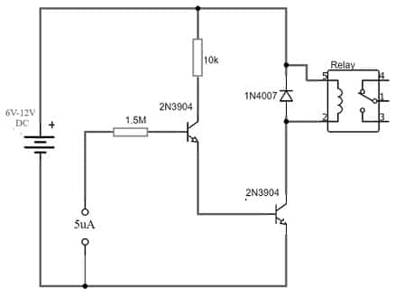
The low current triggered relay circuit with a 2N3904 transistor is shown below. Thus, this circuit is used to activate a relay switch through 5µAmps current only. So this can be done with a bistable relay as well as including some electronic components to make it perform as a monostable relay.
The main variation between these two relays is that a bistable relay simply stays at its final state whenever power is deactivated but consumes 50mAmps minimum trigger current. A monostable relay simply switches back to its actual state whenever the power is deactivated. There is an extensive range of circuits which has an extremely low current output, so this simple circuit can be utilized with them easily.
The required components to make this low current triggered relay circuit mainly include; 2N3904 transistors, 1N4007 diode, 5V relay, 1.5M & 10K resistors, 5uA current input, and 6 to 12V DC supply. Connect the circuit as per the diagram shown below.

Low Current Triggered Relay with 2N3904 Transistors
Working
This low current triggered relay circuit uses a battery, two NPN 2N3904 transistors & relay with current limiting resistors. This circuit works with a 6 to 12V battery and the relay’s operating voltage must be similar to the voltage supply. The working of this circuit is, that whenever the power supply is provided to the circuit, then the 5µAmps input current is supplied to the primary transistor, then the amplified output will become the input to the second transistor.
Now a sufficiently large current is given to the base terminal of this NPN transistor & the current supply from base terminal to emitter simply controls the larger current supply of relay coil throughout the NPN transistor from the Collector terminal to Emitter.
The power supply is provided to the relay coil during the transistor’s switching operation, so a maximum current will flow as a result of the coil’s DC resistance. If there is no flow of current throughout the transistor’s base then there is no flow of current to the coil. This simple circuit is utilized in all battery-operated electronic devices with a low current output.
Microphone Preamplifier with 2N3904 Transistor
A Microphone preamplifier circuit pre-amplifies weak audio signals whenever the sound level of the audio source is very low before transmitting it for further amplification.
Generally, a Preamplifier amplifies the audio signal from the audio source to a high voltage gain however it does not include the current gain to drive the output. Thus, the preamplifier’s improved signal is generally transmitted to a power amplifier wherever the current is amplified. Here we are designing a preamplifier circuit using a 2N3904 transistor mainly for a condenser microphone.
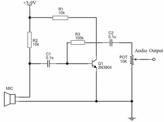
The required components to make this microphone preamplifier circuit mainly include; a Breadboard, 2N3904 NPN transistor, 3-9v battery, 10k potentiometer, connecting wires, 10k & 100k resistors, 0.1uF ceramic capacitor, condenser MIC, and a 8-ohm speaker. Connect the circuit as per the diagram shown below.

Microphone Preamplifier with 2N3904 Transistor
Working
This microphone preamplifier circuit’s operating voltage ranges from 3V to 9V DC. So, the 10KΩ resistor on the positive terminal of microphones offers the required voltage level for the circuit operation. The 0.1μF capacitor in the circuit stops the DC component of the transmission and allows the AC input of the microphone to go into the base terminal of Q1. The 10KΩ resistor connected to the collector terminal of this transistor simply allows the AC component triggering, while the 100KΩ resistor works as a collector coupling resistor.
After that, the o/p audio signal is obtained from the transistor’s collector terminal and transmitted to a loudspeaker through the C2 capacitor. Here, a 10KΩ potentiometer is useful in tuning the gain.
Connecting a base resistor to the base terminal of the transistor is mandatory to avoid it being damaged. So, Please refer to this link for; Choosing Base Resistance for Transistors in Electronic Circuits.
Applications
The applications of the 2N3904 transistor include the following.
- 2N3904 transistor is used in any electronic applications to switch different loads that need current below 200mA like relays, LEDs, high-power transistors, and a part of an electronic circuit.
- It can be used as an amplifier within audio amplification stages to drive tiny speakers.
- This transistor is used as an audio preamplifier in RF application amplification stages.
- The 2N3904 transistor is used widely in a wide range of applications which are discussed below.
- Amplification: This transistor is frequently used as an amplifier within low-power audio, RF, and video applications. Thus, it provides voltage & current gain to different circuits like oscillator circuits, small-signal amplifiers, and audio preamplifiers.
- Switching: This transistor is used as a switch in low-power and digital applications. So, it is used frequently as a switch to Lights, power relays & other loads.
- Oscillators: It is used in oscillator circuits which need a reliable frequency output.
- Voltage Regulator Circuits: This transistor is used in voltage regulator circuits to change the output voltage of a power source. So, it can also be used in switching regulator circuits in power supply to change voltage levels effectively.
- It is used in signal processing circuits like; filters and equalizers to adjust or shape the audio (or) visual signal’s frequency response.
Please refer to this link for the 2N3904 Datasheet.
Thus, this is an overview of the 2N3904 transistor, pinout, specifications, circuit, working, and its applications. Thus, this is a versatile transistor, used frequently in low-power circuits due to its low cost, low noise & high gain properties. Here is a question for you, what is a 2N3906 transistor?